


12
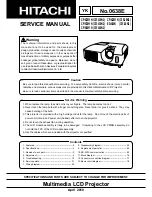
CP-X2511N(C15I-25N2) / CP-X3011N(C15I-30N2) / CP-X4011N(C15I-40N2) / CP-X2011N(C15-20N2) / ED-X45N(C15-20N2)
Lamp does not light
What
is the state of
LAMP indicator D303
during operation?
Is
the LAMP
installation correct
?
Light
install the Lamp
PWB assembly
MAIN
Does
the voltage of
the pin #4 of E814
on the PWB assembly
MAIN change from 4.3V
to 2.8V during
warming-
up?
NG
NO
Change
the lamp. Does
lamp light?
Lamp
Light
YES
Yes
Power unit (ballast)
Power unit (circuit)
What
is the state of
TEMP indicator
D302?
Thermistor
( E1 or E2 )
Is
the voltage
at the (1) of E814 on the
PWB assembly MAIN set to
"L" during warming-
up?
Not light
and blink
PWB assembly MAIN
YES
“L” = 0V
Power unit (ballast)
No
Are
the voltage
supplied to the
pin (2) of connectors**
for DC fans soon after
the button is
pressed?
Observe
the voltage
waveforms at pin (1)
of connectors for DC fans**
soon after the button
is pressed.
Blinks
DC fan
(failed in above check)
Correct waveform is drawn below.
f
≥
40Hz
PWB assembly
MAIN
NO (0V)
PWB assembly
MAIN
Correct
YES
incorrect
*: Be sure to unplug the power cord
before measuring resistance.
Not light
**: DC fan connectors are E801, E802,
E806 and E807.
(5V or higher)
Lights
Measure
resistance of
thermistors E1 and E2
after disconnecting
them from MAIN
board.
OK
PWB assembly
MAIN
E1: 5 to 20k
Ω
E2: 5 to 20k
Ω
NG
(open / short)
Not light