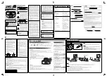
Troubleshooting
6-3
No Search Operation
MIRR, SIC1-38
output is nrmal?
Actual velocity occurs
at SIC1-73 terminal?
Actual velocity occurs
at ISC4-32, 33 terminal?
Check RIC1 peripheral circuit.
RFAGCO, RIC1-89
output level is normal?
Check SIC1 peripheral circuit.
Check SIC4 peripheral circuit.
No
No
No
No
Yes
TE occurs in
search range?
Focus On?
Yes
Yes
Yes
A
See "Fine Seek Check"
No
Yes
Check pick-up.
No
FINE SEEK Check
FINE SEEK MIRR
signal (RIC1-57) is missing?
TZCO signal
(SIC1-52) is occurs?
Track incomming is
delayed?
TE is within
2V and 3V?
Pick-up transfer smooth.
Check RIC1 Peripheral curcuit.
Check SIC1 Peripheral curcuit.
Time out due to many jump counts.
Check SIC1 peripheral circuit.
SIC1-76 output
is normal?
SIC4-28, 29
terminal outputs are
normal?
Check DCN1 and pick-up.
Check MECHA.
Check RIC1-36 terminal.
Check SIC4 peripheral circuit.
Yes
Yes
Yes
Yes
Yes
Yes
Yes
No
No
No
No
No
No
No
Summary of Contents for DVC-605U
Page 59: ...4 24 Disassembly and Reaasembly MEMO ...
Page 79: ...Circuit Descriptions 5 20 MEMO ...
Page 91: ...Troubleshooting 6 12 MEMO ...
Page 92: ...7 1 7 Exploded View 7 1 Cabinet Assembly 7 2 Deck Assembly Page 7 2 7 3 ...
Page 94: ...Exploded Views 7 3 7 2 Deck Assembly 107 906 108 TS16391 ...
Page 95: ...Exploded Views 7 4 MEMO ...
Page 97: ...8 2 Replacement Parts List MEMO ...
Page 99: ...Block Diagram 9 2 MEMO ...
Page 101: ...PCB Diagrams 10 2 10 1 S M P S ...
Page 102: ...PCB Diagrams 10 3 10 2 Main COMPONENT SIDE SOLDER SIDE ...
Page 103: ...PCB Diagrams 10 4 10 3 Jack ...
Page 104: ...PCB Diagrams 10 5 10 4 Front COMPONENT SIDE SOLDER SIDE ...
Page 105: ...PCB Diagrams 10 6 10 5 Key COMPONENT SIDE SOLDER SIDE ...
Page 106: ...PCB Diagrams 10 7 10 6 Deck 10 8 Sensor 10 7 Motor 10 9 Switch ...
Page 107: ...PCB Diagrams 10 8 MEMO ...
Page 108: ...11 1 11 Wiring Diagram ...
Page 109: ...Wiring Diagram 11 2 MEMO ...
Page 111: ...Schematic Diagrams 12 2 12 1 S M P S ...
Page 112: ...Schematic Diagrams 12 3 12 2 Main Micom ...
Page 113: ...Schematic Diagrams 12 4 12 3 Servo ...
Page 114: ...Schematic Diagrams 12 5 12 4 RF ...
Page 115: ...Schematic Diagrams 12 6 12 5 Data Processor ...
Page 116: ...Schematic Diagrams 12 7 12 6 AV Decoder ...
Page 117: ...Schematic Diagrams 12 8 12 7 Video ...
Page 118: ...Schematic Diagrams 12 9 12 8 Audio ...
Page 119: ...Schematic Diagrams 12 10 12 9 Audio 5 1 Channel ...
Page 120: ...Schematic Diagrams 12 11 12 10 AV Interface ...
Page 121: ...Schematic Diagrams 12 12 12 11 Front Micom ...
Page 122: ...Schematic Diagrams 12 13 12 12 Key ...
Page 123: ...Schematic Diagrams 12 14 12 13 Deck ...
Page 124: ...Schematic Diagrams 12 15 12 14 Motor Switch Sensor ...
Page 125: ...Schematic Diagrams 12 16 12 15 Remote Control ...


