


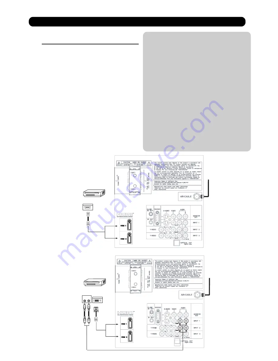
CONNECTING A COMPONENT SOURCE WITH HDMI OR
DVI CAPABILITY TO HDMI 1, HDMI 2 OR HDMI FRONT
1. Connect the HDMI or DVI to HDMI connection
cable from the output of the HDTV set top box
or DVD player to the HDMI
input as shown
on the Rear panel below.
2.
With DVI output, connect the cable from the
AUDIO OUT R of the HDTV set top box or DVD
player to the INPUT (AUDIO/R) jack as shown on
the Rear Panel below.
3.
With DVI output, connect the cable from the
AUDIO OUT L of the HDTV set top box or DVD
player to the INPUT (AUDIO/L) jack as shown
on the Rear Panel below.
4. Press the INPUTS button, then select HDMI 1, 2
or FRONT to view the program from the HDTV
SET TOP BOX or DVD player.
5. Select CABLE or AIR from the INPUTS menu to
return to the last channel viewed.
NOTE:
1. Completely insert the connection cord
plugs when connecting to rear panel jacks.
The picture and sound that is played back
will be abnormal if the connection is loose.
2. The HDMI input on HDMI 1 , 2 and FRONT
contains the copy protection system called
High-bandwidth Digital Content Protection
(HDCP). HDCP is a cryptographic system
that encrypts video signals when using
HDMI connections to prevent illegal
copying of video contents.
3. HDMI is not a “NETWORK” technology. It
establishes a one-way point-to-point
connection for delivery of uncompressed
video to a display.
4. The connected digital output device
controls the HDMI interface so proper set-up
of device user settings determines final
video appearance.
5. When using a DVI to HDMI cable, connect the
Audio Out L and R cables at the same INPUT
(1 , 2 or Front) as your HDMI INPUT(1 , 2 or Front).
(For FRONT INPUT see page 16 for reference).
Connecting External Video Sources
HDTV Set-Top-Box or
DVD Player
DIGITAL OUTPUT
Back of
HDTV Set-Top-Box or
DVD Player
HDMI
Cable
or
L
R
OUTPUT
DIGITAL OUTPUT
DVI to HDMI
Cable
Back of HDTV
Set-Top-Box
or DVD Player
HDMI input
DVI to HDMI Input
CABLE
or
Air signal
HDTV Set-Top-Box or
DVD Player
or
CABLE
or
Air signal
or
39
Summary of Contents for Director's P60X901
Page 66: ...DW3U 65 FINAL WIRING DIAGRAM TABLE OF CONTENTS ...
Page 82: ...FINAL ASSEMBLY GUIDE TABLE OF CONTENTS 81 DW3U ...
Page 83: ...FINAL ASSEMBLY GUIDE 82 DW3U ...
Page 84: ...FINAL ASSEMBLY GUIDE 83 DW3U ...
Page 85: ...FINAL ASSEMBLY GUIDE 84 DW3U ...
Page 86: ...FINAL ASSEMBLY GUIDE 85 DW3U ...
Page 87: ...FINAL ASSEMBLY GUIDE 86 DW3U ...
Page 88: ...FINAL ASSEMBLY GUIDE 87 DW3U ...
Page 89: ...FINAL ASSEMBLY GUIDE 88 DW3U ...
Page 90: ...FINAL ASSEMBLY GUIDE 89 DW3U ...
Page 91: ...FINAL ASSEMBLY GUIDE 90 DW3U ...
Page 92: ...FINAL ASSEMBLY GUIDE 91 DW3U ...
Page 93: ...FINAL ASSEMBLY GUIDE 92 DW3U ...
Page 94: ...FINAL ASSEMBLY GUIDE 93 DW3U ...
Page 95: ...FINAL ASSEMBLY GUIDE 94 DW3U ...
Page 96: ...FINAL ASSEMBLY GUIDE 95 DW3U ...
Page 97: ...FINAL ASSEMBLY GUIDE 96 DW3U ...
Page 112: ...BACK TO TABLE OF CONTENTS 111 PRINTED CIRCUIT BOARDS DW3 U TERMINAL PWB Component side DW3 U ...
Page 113: ...PRINTED CIRCUIT BOARDS DW3 U TERMINAL PWB Solder side DW3 U 112 ...
Page 115: ...PRINTED CIRCUIT BOARDS DW3 SD CARD PWB Included on Terminal PWB Ass y DW3 U 114 Solder side ...
Page 117: ...PRINTED CIRCUIT BOARDS DW3 U FILTER PWB Component side DW3 U 116 Component side ...
Page 118: ...PRINTED CIRCUIT BOARDS DW3 U FILTER PWB Solder side DW3 U 117 Solder side ...
Page 121: ...PRINTED CIRCUIT BOARDS DW3 U POD PWB DW3 U 120 Component side ...
Page 122: ...PRINTED CIRCUIT BOARDS DW3 U POD PWB DW3 U 121 Solder side ...
Page 123: ...PRINTED CIRCUIT BOARDS DW3 U SWITCH PWB DW3 U 122 Component side Solder side ...
Page 143: ......


