background image

* ALTERNATIVE PARTS

--- 5 ---

9 -- 07

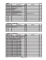
PARTS

ITEM

NO.

CODE NO.

DESCRIPTION

REMARKS

NO.

USED

DH 50MRY

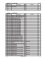
STANDARD  ACCESSORIES

ITEM

NO.

CODE NO.

DESCRIPTION

REMARKS

NO.

USED

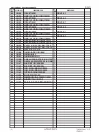
OPTIONAL  ACCESSORIES

ITEM

NO.

CODE NO.

DESCRIPTION

REMARKS

NO.

USED

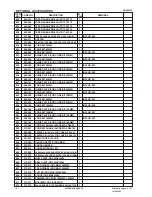
137

999-074

CARBON BRUSH (AUTO STOP TYPE) (1 PAIR)

1

138

938-477

HEX. SOCKET SET SCREW M5X8

2

139

328-918

BEARING HOLDER

1

140

328-919

TAIL COVER

1

141

328-914

CASE (B)

1

*

142

328-911

CONTROLLER CIRCUIT 110V-115V

1

*

142

328-912

CONTROLLER CIRCUIT 120V

1

*

142

328-913

CONTROLLER CIRCUIT 220V-240V

1

*

143

317-113

INTERNAL WIRE

1

EXCEPT FOR USA, CAN

144

326-541

VINYL TUBE (I.D.9.5XT0.56X85)

1

501

981-840

GREASE (A) FOR HAMMER. HAMMER DRILL (30G)

1

502

328-921

CASE (PLASTIC)

1

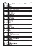
601

308-471

GREASE FOR HAMMER. HAMMER DRILL (70G)

1

602

980-927

GREASE FOR HAMMER. HAMMER DRILL (500G)

1

603

320-859

SYRINGE (BLOW-OUT BULB TYPE)

1

604

318-085

SYRINGE (BELLOWS TYPE)

1

605

313-448

DRILL BIT (SDS MAX) D16X340

1

606

313-456

DRILL BIT (SDS MAX) D16X540

1

607

313-449

DRILL BIT (SDS MAX) D19X340

1

608

313-457

DRILL BIT (SDS MAX) D19X540

1

609

313-450

DRILL BIT (SDS MAX) D22X320

1

610

313-458

DRILL BIT (SDS MAX) D22X520

1

611

313-451

DRILL BIT (SDS MAX) D25X320

1

612

313-459

DRILL BIT (SDS MAX) D25X520

1

613

313-452

DRILL BIT (SDS MAX) D28X370

1

614

313-460

DRILL BIT (SDS MAX) D28X570

1

615

313-453

DRILL BIT (SDS MAX) D32X370

1

616

313-461

DRILL BIT (SDS MAX) D32X570

1

617

313-454

DRILL BIT (SDS MAX) D38X370

1

618

313-462

DRILL BIT (SDS MAX) D38X570

1

619

313-455

DRILL BIT (SDS MAX) D40X370

1

620

313-463

DRILL BIT (SDS MAX) D40X570

1

621

944-460

TAPER SHANK DRILL BIT D11X100

1

Summary of Contents for DH 50MR

Page 1: ...os DH 50MRY E499 DH 50MR E498 Sep 2007 Drilling holes in concrete and drilling anchor holes Demolishing and chiseling of concrete Edging gravel road digging compacting and tamping grooving cutting stripping and roughing etc MARKETING OBJECTIVE APPLICATIONS SELLING POINTS International Sales Division D New features Equipped with a pendulum dynamic absorber as the low vibration mechanism Model DH 50...

Page 2: ...ki com manual_view_export Throughout this TECHNICAL DATA AND SERVICE MANUAL a symbol s is are used in the place of company name s and model name s of our competitor s The symbol s utilized here is are as follows Competitors Symbols utilized Company name Model name B BOSCH GBH 11DE C MAKITA HR5211C ...

Page 3: ...MPARISONS WITH SIMILAR PRODUCTS 9 1 Specifications comparisons 9 PRECAUTIONS IN SALES PROMOTION 10 1 Safety instructions 10 REFERENCE MATERIALS 11 REPAIR GUIDE 12 1 Precautions in disassembly and reassembly 12 STANDARD REPAIR TIME UNIT SCHEDULES 19 Assembly diagram for DH 50MRY Assembly diagram for DH 50MR ...

Page 4: ...erformance in the class We conducted digital engineering to determine the optimal impact specifications As a result the Models DH 50MRY and DH 50MR offer the fastest drilling speed and greatest chiseling performance in the class Based on our own research Test conditions Direction Downward drilling Pushing force 98 N 10 kgf Test material Concrete panel with a compression strength of 2 352 N cm2 240...

Page 5: ...ion to the operator s arms Dial type constant speed with variable speed control The Model DH 50MRY DH 50MR is equipped with a built in electronic control circuit that can adjust the number of hammering steplessly between 1 050 and 2 150 min 1 with the dial Even though the load varies the Model DH 50MRY DH 50MR provides better operability and stable and efficient drilling performance because the co...

Page 6: ...tral and Hammering only The Models DH 50MRY DH 50MR provides three functions rotation hammering function for drilling neutral function for positioning the tool tip and hammering only function for chiseling and chipping These function modes can be easily switched by using the change lever The tool angle can be easily changed in 12 steps by turning the grip with the change lever positioned at Neutra...

Page 7: ... crank cover back cover Polycarbonate resin Housing Paint Green black gun metallic silver silver Switch Trigger switch Type of handles D shaped handle and side handle Full load rotation rate min 1 110 230 Full load impact rate min 1 1 050 2 150 Packaging Corrugated cardboard box with plastic tool case Product 10 5 23 1 10 0 22 0 Weight Packed kg lbs 16 0 35 2 15 5 34 1 Standard accessories Plastic...

Page 8: ... 16 313454 38 1 1 2 570 22 7 16 313462 40 1 9 16 370 14 9 16 313455 40 1 9 16 570 22 7 16 313463 2 Drilling work for anchor holes Rotation Hammering Drill bit Taper shank 1 Drill bit Taper shank 2 Taper shank adapter 3 Cotter D mm L mm Code No Taper dimension Code No Code No 11 0 7 16 100 4 944460 12 3 15 32 110 4 5 16 944461 14 3 9 16 110 4 5 16 944462 Morse taper No 1 313464 944477 14 5 9 16 110...

Page 9: ...7 32 94 3 11 16 100 3 15 16 105 4 1 8 120 4 3 4 125 4 29 32 133 5 1 4 955165 300 11 13 16 313467 4 Hole drilling 13 mm drill chuck 13VLD D with chuck wrench Chuck adapter Code No Code No 321813 313468 5 Chemical anchor holes drilling work Rotation Hammering Socket square size mm Code No 12 7 1 2 313469 19 0 3 4 313470 l L Chuck adapter SDS max shank Chuck wrench 13 mm drill chuck 13VLD D Chemical ...

Page 10: ... mm Code No 280 11 313473 400 15 3 4 313474 8 Cutting and stripping Asphalt cutting etc Hammering mode Cutter SDS max shank L mm Width mm Code No 400 15 3 4 50 2 313475 9 Scooping work Hammering mode Scoop SDS max shank L mm Code No 400 15 3 4 313476 10 Surface roughing work Hammering Bushing tool Shank SDS max shank Code No L mm Code No 313477 220 8 21 32 313479 L L L L L ...

Page 11: ...3478 220 8 21 32 313479 12 Syringe for chip removal Syringe Code No Bellows 318085 Blow out bulb 320859 13 Grease Code No Code No 980927 981840 Note Code numbers listed above are subject to change without notice Please refer to periodic Technical News Bulletins l L 500 g 1 1 lbs Can 30 g 1 oz Tube ...

Page 12: ...l load rotation rate min 1 110 230 120 250 130 260 120 250 Full load impact rate min 1 1 050 2 150 1 200 2 150 1 075 2 150 1 100 2 250 Full load vibration level Tri axial measured m s2 11 7 17 8 26 0 13 5 21 0 No load noise level measured dB 81 81 83 81 82 Full load noise level measured dB 98 98 98 98 97 Length 570 22 7 16 495 19 1 2 599 23 5 8 595 23 7 16 Height 285 11 7 32 293 11 9 16 287 11 5 1...

Page 13: ... use of any electric tool cannot be completely eliminated Accordingly general precautions and suggestions for the use of electric power tools and specific precautions and suggestions for the use of the Rotary Hammers are listed in the Handling Instructions to enhance the safe efficient use of the tool by the customer Salespersons must be thoroughly familiar with the contents of the Handling Instru...

Page 14: ...se and the crank case connecting rod side with 70 g of grease Take care not to overfill the grease as an excessive amount of grease can cause hammering failure The gear change section inside the gear cover uses Hitachi Motor Grease No 29 The proper amount of grease is 30 g Never use the special grease for the hammering section in the gear change section Otherwise the special grease will leak into ...

Page 15: ...ket Hd Bolt M8 x 25 7 Then the Retainer Sleeve 19 Second Hammer 21 Cylinder 26 Striker 31 etc can be pulled out of the Cylinder Case 37 in an assembly state as shown in Fig 3 Remove the Clutch Spring 30 Lock Spring 27 and Spring Holder B 29 from this assembly Turn the Retainer Sleeve 19 and remove the eight Needle Pins D8 x 6 25 to separate the Retainer Sleeve 19 from the Cylinder 26 Remove the Se...

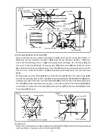
Page 16: ...4DDCMPS2L 82 with a retaining ring puller At this time turn the Crank Shaft 79 so that the hole of the Retaining Ring for D47 Hole 81 can be seen before removal Fig 4 Press the end face of the Crank Shaft 79 with a hand press to remove the First Gear 116 Second Pinion 117 and Crank Shaft 79 from the Crank Case 115 Fig 5 Fig 4 Fig 5 e Slip Cluch Refer to the Technical Data and Service Manual for th...

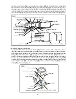
Page 17: ...de diameter of the Piston 35 Mount the O ring 32 to the Piston 35 to make the piston ass y Move the crank pin of the Crank Shaft 79 to the bottom dead center and mount the piston ass y to the Crank Shaft 79 from the Cylinder Case 37 side of the Crank Case 115 Mount the Retaining Ring for D12 Shaft 78 using a retaining ring puller Fig 7 c Cylinder 26 and Retainer Sleeve 19 Mount the Retainer Damper...

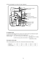
Page 18: ... 95 engaging the convex portion of the Base 91 with the concave portion of the Spring Holder 95 then secure it with the Seal Lock Hex Socket Hd Bolt M5 x 16 96 At this time apply Hitachi Motor Grease No 29 to the tip of the Leaf Spring 93 where the Weight 88 contacts Insert the two Weight Bumpers 94 into the back of the Base 91 so that the rounded portion of the Weight Bumper 94 contacts the Weigh...

Page 19: ... torque Apply screw locking agent TB1401 to all hex socket head bolts M4 M5 M6 and M8 Note Be sure to apply screw locking agent Three Bond TB1401 to the threads during reassembly Otherwise the bolts loosened with vibration may cause damage to the tool body M8 Hex Socket Hd Bolt W Flange M8 x 35 38 for mounting the cylinder case 19 6 N m 200 kgf cm M8 Seal Lock Hex Socket Hd Bolt M8 x 25 7 for moun...

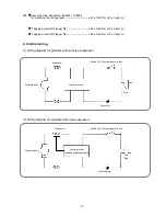
Page 20: ...ge D4 1 96 0 49 N m 20 5 kgf cm 4 Internal wiring 1 Wiring diagram for products without noise suppressor 2 Wiring diagram for products with noise suppressor Controller circuit including noise suppressor Switch B 1P screw type w o lock Stator ass y Plug Armature ass y Pillar terminal Controller circuit Switch B 1P screw type w o lock Stator ass y Plug Armature ass y Connector ...

Page 21: ...inute with no abnormalities 220 V 240 V and 110 V for U K products AC 2 500 V 1 minute with no abnormalities 110 V 127 V except U K products 6 No load current value After no load operation for 30 minutes the no load current value should be as follows Voltage V 110 120 220 230 240 Current A max 7 3 6 3 3 7 3 5 3 4 Lead wires of switch and cord Tab Case A Lead wire of stator Housing Tail cover Lead ...

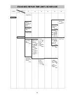
Page 22: ...CM Sleeve Retainer Damper Retainer Sleeve Second Hammer Damper Control Circuit Back Cover Weight Base Leaf Spring Spring Holder Striker Piston Piston Pin Connecting Rod Gear Cover Needle Bearing Armature Ass y Ball Bearing 6202DD Ball Bearing 6201VV Crank Shaft Ball Bearing 6204DD First Gear Second Pinion Slip Clutch Ass y Cylinder Lock Sleeve Spring Holder B Clutch Bevel Gear Cylinder Case Housin...

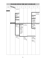
Page 23: ...g Ball Bearing 6008CM Sleeve Retainer Damper Retainer Sleeve Second Hammer Damper Control Circuit Back Cover Striker Piston Piston Pin Connecting Rod Gear Cover Needle Bearing Armature Ass y Ball Bearing 6202DD Ball Bearing 6201VV Crank Shaft Ball Bearing 6204DD First Gear Second Pinion Slip Clutch Ass y Cylinder Lock Sleeve Spring Holder B Clutch Bevel Gear Cylinder Case Housing Ass y Stator Ass ...

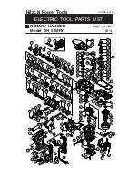
Page 24: ...2 35 36 37 38 39 41 42 43 44 45 49 50 51 46 47 48 77 78 79 80 81 82 83 84 114 85 86 111 97 98 99 100 101 102 103 104 105 106 107 108 109 110 112 113 68 52 55 60 57 58 61 59 115 116 117 118 119 120 60 136 135 137 133 138 140 66 122 121 135 130 131 132 125 126 127 128 129 141 142 143 501 502 14 16 40 54 53 62 63 64 65 66 67 56 70 73 71 72 74 75 76 139 74 87 88 89 91 92 93 90 96 124 123 67 69 144 133...

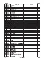
Page 25: ...G 1 21 328 885 SECOND HAMMER 1 22 328 886 DAMPER WASHER 1 23 328 887 DAMPER 1 24 328 888 DAMPER HOLDER 1 25 328 891 NEEDLE PIN D8X6 4 26 328 889 CYLINDER 1 27 328 895 LOCK SPRING 1 28 318 562 LOCK SLEEVE 1 29 328 892 SPRING HOLDER B 1 30 328 893 CLUTCH SPRING 1 31 328 890 STRIKER 1 32 328 880 O RING 2 33 328 894 CLUTCH 1 34 328 879 PISTON PIN 1 35 328 877 PISTON 1 36 328 878 CONNECTING ROD 1 37 32...

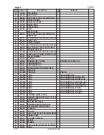
Page 26: ...CORD ARMOR D8 8 1 73 938 051 CORD ARMOR D10 1 1 74 984 750 TAPPING SCREW W FLANGE D4X16 4 75 960 266 CORD CLIP 1 75 981 987Z CORD CLIP 1 FOR SUI 76 500 390Z CORD 1 CORD ARMOR D8 8 76 500 235Z CORD 1 CORD ARMOR D8 8 FOR INA IND 76 500 408Z CORD 1 CORD ARMOR D8 8 FOR NZL AUS 76 500 453Z CORD 1 CORD ARMOR D10 1 FOR USA CAN 76 500 446Z CORD 1 CORD ARMOR D8 8 FOR GBR 230V 76 500 460Z CORD 1 CORD ARMOR ...

Page 27: ...K CASE 1 116 328 870 FIRST GEAR 1 117 328 871 SECOND PINION 1 118 939 299 NEEDLE BEARING M661 1 119 953 121 HEX HD TAPPING SCREW D5X50 2 120 340 712C STATOR ASS Y 110V 115V 1 INCLUD 121 120 340 712G STATOR ASS Y 120V 1 INCLUD 121 120 340 712E STATOR ASS Y 220V 230V 1 INCLUD 121 120 340 712F STATOR ASS Y 240V 1 INCLUD 121 121 958 032 BRUSH TERMINAL 2 122 321 313 SEAL LOCK HEX SOCKET HD BOLT M6X22 2...

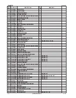
Page 28: ...STIC 1 601 308 471 GREASE FOR HAMMER HAMMER DRILL 70G 1 602 980 927 GREASE FOR HAMMER HAMMER DRILL 500G 1 603 320 859 SYRINGE BLOW OUT BULB TYPE 1 604 318 085 SYRINGE BELLOWS TYPE 1 605 313 448 DRILL BIT SDS MAX D16X340 1 606 313 456 DRILL BIT SDS MAX D16X540 1 607 313 449 DRILL BIT SDS MAX D19X340 1 608 313 457 DRILL BIT SDS MAX D19X540 1 609 313 450 DRILL BIT SDS MAX D22X320 1 610 313 458 DRILL ...

Page 29: ...955 157 CORE BIT 79MM 1 INCLUD 645 645 955 168 GUIDE PLATE FOR CORE BIT 79MM 1 646 956 004 CORE BIT 94MM 1 INCLUD 647 647 956 005 GUIDE PLATE FOR CORE BIT 94MM 1 648 955 159 CORE BIT 105MM 1 INCLUD 649 649 955 169 GUIDE PLATE FOR CORE BIT 105MM 1 650 956 006 CORE BIT 120MM 1 INCLUD 651 651 956 007 GUIDE PLATE FOR CORE BIT 120MM 1 652 956 728 CORE BIT 150MM 1 INCLUD 653 653 956 743 GUIDE PLATE FOR ...

Page 30: ...31 32 33 34 32 35 36 37 38 39 41 42 43 44 45 49 50 51 46 47 48 77 78 79 80 81 82 83 84 104 85 86 101 87 88 89 90 91 92 93 94 95 96 97 98 99 100 102 103 68 52 55 60 57 58 61 59 105 106 107 108 109 110 60 126 125 127 123 128 130 66 112 111 121 122 115 116 117 118 119 131 132 134 501 502 14 16 40 54 53 62 63 64 65 66 67 56 70 73 71 72 74 75 76 129 74 114 113 67 69 123 124 125 133 120 ...

Page 31: ...G 1 21 328 885 SECOND HAMMER 1 22 328 886 DAMPER WASHER 1 23 328 887 DAMPER 1 24 328 888 DAMPER HOLDER 1 25 328 891 NEEDLE PIN D8X6 4 26 328 889 CYLINDER 1 27 328 895 LOCK SPRING 1 28 318 562 LOCK SLEEVE 1 29 328 892 SPRING HOLDER B 1 30 328 893 CLUTCH SPRING 1 31 328 890 STRIKER 1 32 328 880 O RING 2 33 328 894 CLUTCH 1 34 328 879 PISTON PIN 1 35 328 877 PISTON 1 36 328 878 CONNECTING ROD 1 37 32...

Page 32: ...ORD ARMOR D8 8 1 73 938 051 CORD ARMOR D10 1 1 74 984 750 TAPPING SCREW W FLANGE D4X16 4 75 960 266 CORD CLIP 1 75 981 987Z CORD CLIP 1 FOR SUI 76 500 390Z CORD 1 CORD ARMOR D8 8 76 500 235Z CORD 1 CORD ARMOR D8 8 FOR INA IND 76 500 408Z CORD 1 CORD ARMOR D8 8 FOR NZL AUS 76 500 453Z CORD 1 CORD ARMOR D10 1 FOR USA CAN 76 500 446Z CORD 1 CORD ARMOR D8 8 FOR GBR 230V 76 500 460Z CORD 1 CORD ARMOR D...

Page 33: ... TERMINAL 2 112 321 313 SEAL LOCK HEX SOCKET HD BOLT M6X22 2 113 980 750 GUIDE PLATE 1 114 980 727 HANDLE RUBBER 1 115 620 2DD BALL BEARING 6202DDCMPS2L 1 116 980 700 DUST WASHER B 1 117 318 918 FAN 1 118 360 819C ARMATURE ASS Y 110V 115V 1 INCLUD 117 118 360 819U ARMATURE ASS Y 120V 1 INCLUD 115 117 120 121 118 360 819E ARMATURE ASS Y 220V 230V 1 INCLUD 117 118 360 819F ARMATURE ASS Y 240V 1 INCL...

Page 34: ...DRILL BIT SDS MAX D32X570 1 617 313 454 DRILL BIT SDS MAX D38X370 1 618 313 462 DRILL BIT SDS MAX D38X570 1 619 313 455 DRILL BIT SDS MAX D40X370 1 620 313 463 DRILL BIT SDS MAX D40X570 1 621 944 460 TAPER SHANK DRILL BIT D11X100 1 622 944 461 TAPER SHANK DRILL BIT D12 3X110 1 623 993 038 TAPER SHANK DRILL BIT D12 7X110 1 624 944 462 TAPER SHANK DRILL BIT D14 3X110 1 625 944 500 TAPER SHANK DRILL ...

Page 35: ... 313 466 CORE BIT SHANK B SDS MAX D25 35 1 655 313 467 CORE BIT SHANK A SDS MAX D38 150 1 656 956 009 CENTER PIN B 147L FOR CORE BIT D32 35 1 657 955 165 CENTER PIN A 133L FOR CORE BIT D38 150 1 658 321 813 DRILL CHUCK 13VLD D 1 659 313 468 CHUCK ADAPTER SDS MAX 1 660 303 334 CHUCK HANDLE 1 661 930 515 CHUCK WRENCH 10G 1 662 313 469 CHEMICAL ANCHOR ADAPTER SDS MAX 12 7MM 1 663 313 470 CHEMICAL ANC...

Reviews: