-12-
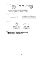
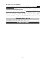
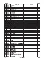
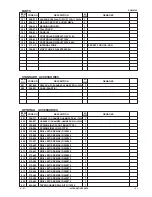
Front Cap
[1]
Grip
[2]
Stopper Ring
[3]
Needle Rollers D8 x 20
[18]
Needle Holder
[4]
Retainer Spring
[5]
Spring Holder
[6]
Retainer Sleeve
[19]
Be sure to disconnect the power cord plug from the wall outlet before repairing. Otherwise, the motor turns
abruptly and it is very dangerous.
1. Precautions in disassembly and reassembly
The
[Bold]
numbers in the description below correspond to the item numbers in the Parts List and the
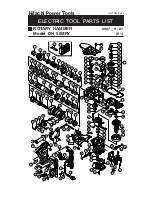
exploded assembly diagram for the Models DH 50MRY/DH 50MR.
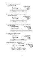
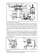
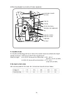
1. Disassembly of the tool retainer
Pull the Grip
[2]
in the arrow direction to full as shown in Fig. 1. Remove the Front Cap
[1]
.
(Front Cap
[1]
is fitted securely. Pull the Front Cap
[1]
forcefully to remove.) Thus the Grip
[2]
can be removed from the
Retainer Sleeve
[19]
.
Remove the Stopper Ring
[3]
using a retaining ring puller. Then the Needle Holder
[4]
, two Needle
Rollers D8 x 20
[18]
, Retainer Spring
[5]
and Spring Holder
[6]
can be removed from the Retainer Sleeve
[19]
. (Fig. 2)
Fig. 1 Fig.
2
2. Disassembly of the hammering mechanism and the vibration reduction mechanism
(a) Second Hammer
[21]
and Striker
[31]
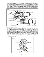
Remove the Seal Lock Hex. Socket Hd. Bolt M8 x 25
[7]
. Then the Retainer Sleeve
[19]
, Second
Hammer
[21]
, Cylinder
[26]
, Striker
[31]
, etc. can be pulled out of the Cylinder Case
[37]
in an assembly
state as shown in Fig. 3. Remove the Clutch Spring
[30]
, Lock Spring
[27]
and Spring Holder (B)
[29]
from this assembly. Turn the Retainer Sleeve
[19]
and remove the eight Needle Pins D8 x 6
[25]
to
separate the Retainer Sleeve
[19]
from the Cylinder
[26]
. Remove the Second Hammer
[21]
from the
separated Retainer Sleeve
[19]
together with the Damper Holder
[24]
, Damper
[23]
and Damper Washer
[22]
. Remove the Striker
[31]
by tapping the end face of the separated Cylinder
[26]
with a plastic
hammer (Fig. 3).
(b) Piston
[35]
Remove each bolt fixing the Lever Holder
[45]
, Hood
[59]
and Crank Cover
[86]
to the Cylinder Case
[37]
and the Crank Case
[115]
. Remove the Hex. Socket Hd. Bolt (W/Flange) M8 x 35
[38]
. Then the
Cylinder Case
[37]
can be removed from the Crank Case
[115]
. To remove the Piston
[35]
, remove the
Retaining Ring for D12 Shaft
[78]
using a retaining ring puller and remove the Connecting Rod
[36]
from
the Crank Shaft
[79]
(Fig. 3).
(c) Vibration reduction mechanism
Remove the Seal Lock Hex. Socket Hd. Bolt M5 x 30
[90]
from the Crank Case
[115]
. Then the vibration
reduction mechanism such as the Weight
[88]
, Leaf Spring
[93]
, etc. can be pulled out as the weight
ass'y (Fig. 3).
Disassembly
REPAIR GUIDE

