background image

10

English

ASSEMBLY AND OPERATION

APPLICATIONS

Rotation and hammering function

Drilling anchor holes

Drilling holes in concrete

Hammering function only

Crushing concrete, chipping, digging, and squaring
(by applying optional accessories)

PRIOR TO  OPERATION

1. Power source

Ensure that the power source to be utilized conforms to the power source
requirements specified on the product nameplate.

2. Power switch

Ensure that the switch is in the OFF position. If the plug is connected to a
receptacle while the switch is in the ON position, the power tool will start operating
immediately and can cause serious injury.

3. Extension cord

When the work area is far away from the power source, use an extension cord of
sufficient thickness and rated capacity (refer to page 9). The extension cord should
be kept as short as practicable.

WARNING:

Damaged cord must be replaced or repaired.

4. Check the receptacle

If the receptacle only loosely accepts the plug, the receptacle must be repaired.
Contact a licensed electrician to make appropriate repairs.
If such a fautly receptacle is used, it may cause overheating, resulting in a serious
hazard.

5. Confirming condition of the environment:

Confirm that the work site is placed under appropriate conditions conforming to
prescribed precautions.

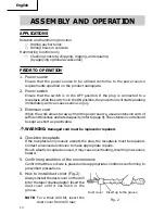
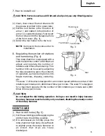
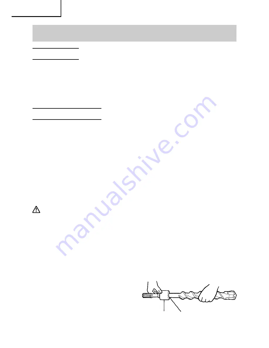
6. How to install dust cover (Fig. 2)

Always install the dust cover on the drill
bit or the taper shank adaptor. Insert the
dust cover until it lies flush in the
groove.

NOTE: For a thick drill bit, insert the

dust cover from drill rear.

Dust cover

Fig. 2

Insert up to the groove

Summary of Contents for DH 40FB

Page 1: ... motorisé INSTRUCTION MANUAL AND SAFETY INSTRUCTIONS WARNING Improper and unsafe use of this power tool can result in death or serious bodily injury This manual contains important information about product safety Please read and understand this manual before operating the power tool Please keep this manual available for others before they use the power tool MANUAL DE INSTRUCCIONES E INSTRUCCIONES ...

Page 2: ...LUS SUR 25 DESCRIPTION FONCTIONNELLE 26 NOM DES PARTIES 26 SPECIFICATIONS 26 Page ASSEMBLAGE ET FONCTIONNEMENT 27 APPLICATIONS 27 AVANT L UTILISATION 27 UTILISATION 28 COMMENT UTILISER LA COURONNE 31 ENTRETIEN ET INSPECTION 33 ACCESOIRES 35 ACCESSOIRES STANDARD 35 ACCESSOIRES SUR OPTION 35 LISTA DES PIÈCES 54 ÍNDICE Página INFORMACIÓN IMPORTANTE 37 SIGNIFICADO DE LAS PALABRAS DE SEÑALIZACIÓN 37 SE...

Page 3: ...section of this Instruction Manual and in the sections which contain the operation and maintenance instructions Hazards that must be avoided to prevent bodily injury or machine damage are identified by WARNINGS on the power tool and in this Instruction Manual Never use this power tool in a manner that has not been specifically recommended by HITACHI unless you first confirm that the planned use wi...

Page 4: ...ee wire grounded power cord and grounded power supply system 2 Avoid body contact with grounded surfaces such as pipes radiators ranges and refrigerators There is an increased risk of electric shock if your body is grounded 3 Don t expose power tools to rain or wet conditions Water entering a power tool will increase the risk of electric shock 4 Do not abuse the cord Never use the cord to carry th...

Page 5: ...ol accidentally 5 Store idle tools out of reach of children and other untrained persons Tools are dangerous in the hands of untrained users 6 Maintain tools with care Keep cutting tools sharp and clean Properly maintained tools with sharp cutting edges are less likely to bind and are easier to control 7 Check for misalignment or binding of moving parts breakage of parts and any other condition tha...

Page 6: ...es which have been mounted to the tool should be secure and tight 14 Keep motor air vent clean The tool s motor air vent must be kept clean so that air can freely flow at all times Check for dust build up frequently 15 Operate power tools at the rated voltage Operate the power tool at voltages specified on its nameplate If using the power tool at a higher voltage than the rated voltage it will res...

Page 7: ... bare hands after operation 4 NEVER wear gloves made of stuff liable to roll up such as cotton wool cloth or string etc 5 ALWAYS attach the side handle and securely grip the Rotary Hammer 6 ALWAYS be careful with buried object such as an underground wiring Touching these active wiring or electric cable with this tool you may receive an electric shock Comfirm if there are any buried object such as ...

Page 8: ...m has no external grounding you must still follow the normal electrical safety precautions given in this Instruction Manual including not using the power tool in wet environments To keep the double insulation system effective follow these precautions 䡬 Only HITACHI AUTHORIZED SERVICE CENTER should disassemble or assemble this power tool and only genuine HITACHI replacement parts should be installe...

Page 9: ...er from those on your own power tool NAME OF PARTS Fig 1 Housing Stopper Switch Trigger Side Handle Handle Nameplate Tail Cover Set Screw Under the Tail Cover Selector Lever Brush Cap Inside the Tail Cover Dial SPECIFICATIONS Motor Single Phase Series Commutator Motor Power Source Single Phase 115 V 60 Hz Current 8 7 A Capacity Drill Bit 1 9 16 40 mm Core Bit 4 1 8 105 mm No Load Speed 180 360 min...

Page 10: ... power source use an extension cord of sufficient thickness and rated capacity refer to page 9 The extension cord should be kept as short as practicable WARNING Damaged cord must be replaced or repaired 4 Check the receptacle If the receptacle only loosely accepts the plug the receptacle must be repaired Contact a licensed electrician to make appropriate repairs If such a fautly receptacle is used...

Page 11: ...djusting the dial depending upon the contents of operation such as boring holes into fragile materials chipping centering etc The scale 1 of the dial is designed for a minimum speed with the number of 180 rotations per minute and 1 400 times of blow per minute The scale 5 is designed for a maximum speed with the number of 360 rotations per minute and 2 800 times of blow per minute CAUTION Do not a...

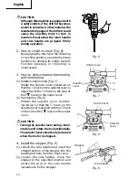
Page 12: ...o that the mark on the selector lever is aligned with the mark on the side of the mark on the under cover 2 Hammering Fig 8 Rotate the selector lever counter clockwise so that the mark on the selector lever is aligned with the mark on the side of the mark on the under cover CAUTION 䡬 Turning the selector lever during motor rotation will rotate the tool accidentally The selector lever should only b...

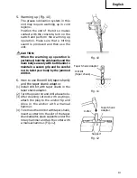
Page 13: ... and be careful not to twist your body by the jammed drill bit 6 How to use the drill bit taper shank and the taper shank adaptor 1 Install drill bit with taper shank in the taper shank adaptor 2 Turn the power on and drill a base hole 3 After cleaning out dust with a syringe attach the plug to the anchor tip and drive in the anchor with a manual hammer 4 To remove the drill bit with taper shank i...

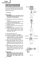
Page 14: ...s not fall even if it faces downward Fig 15 2 How to bore Fig 16 1 Connect the plug to the receptacle 2 A spring is installed in the center pin Push it lightly to the wall or the floor straight Connect all over the surface of the core bit tip and start operating 3 When boring about 3 16 5 mm in depth the position of the hole will establish Bore after that removing the center pin and the guide plat...

Page 15: ...e the core bit shank from the rotary hammer and strike the head of the core bit shank strongly two or three times with a manual hammer holding the core bit then the thread becomes loose and the core bit can be removed Core Bit Shank Fig 17 ...

Page 16: ...it winding is the very heart of the power tool Exercise due care to ensure the winding does not become damaged and or wet with oil or water 4 Inspecting the carbon brushes Fig 18 The motor employs carbon brushes which are consumable parts When they become worn to or near wear limit it could result in motor trouble When an auto stop carbon brush is equipped the motor will stop automatically At that...

Page 17: ...placement of grease 䡬 Grease replenishment CAUTION Before replenishing the grease turn the power off and pull out the power plug 1 Remove the crank case cover and wipe off the grease inside 2 Apply 0 7 oz 20 g of HITACHI Electric Hammer Grease A standard accessory contained in tube to the crank case As the tube contains 1 oz 30 g of grease supply 2 3 of the contained grease 3 After replenishing th...

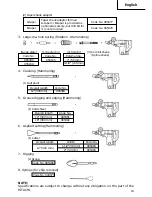
Page 18: ...de No 313078 1 3 Stopper Code No 971786 1 4 Allen Wrench 4 mm Code No 944458 1 5 Allen Wrench 5 mm Code No 944459 1 6 Hammer Grease A Code No 981840 1 7 Dust Cover Code No 993245 1 OPTIONAL ACCESSORIES sold separately For accessories in detail please call HITACHI AT 1 800 59 TOOLS 1 Through hole drilling Rotation Hammering 2 Anchor hole drilling Rotation Hammering Overall length 16 400 mm Code No ...

Page 19: ...8 955169 2 Core bit External dia 2 50 mm 4 1 8 105 mm 1 Center pin Code No 955165 3 Core bit shank Spline shank Taper shank adaptor formed A taper or B taper is provided as optional accessory but drill bit for it is not provided Code No 985377 Code No 985378 A taper B taper 1 Bull point Overall length Code No 12 300 mm 985383 1 Cold chisel Overall length Code No 12 300 mm 985381 18 460 mm 985382 1...

Page 20: ...mploi et dans les sections qui contiennent les instructions de fonctionnement et d entretien Les dangers qui doivent être évités pour prévenir des blessures corporelles ou un endommagement de la machine sont identifiés par AVERTISSEMENTS sur l outil motorisé et dans ce mode d emploi Ne jamais utiliser cet outil motorisé d une manière qui n est pas spécifiquement recommandée par HITACHI sans avoir ...

Page 21: ...ne façon La double isolation élimine le besoin d un cordon d alimentation à trois fils et d un système d alimentation avec mises à la terre 2 Eviter tout contact corporel avec les surfaces mises à la terre telles que les canalisations les radiateurs les réchauds et les réfrigérateurs Il y a un risque accru d électrocution si son corps est mis à la terre 3 Ne pas exposer les outils motorisés à la p...

Page 22: ... la pièce avec la main ou contre son corps est instable et peut conduire à une perte de contrôle de l outil 2 Ne pas forcer sur l outil Utiliser l outil correct pour l application souhaitée L outil correct réalisera un meilleur et plus sûr travail dans le domaine pour lequel il a été conçu 3 Ne pas utiliser un outil s il ne se met pas sous ou hors tension avec un interrupteur Un outil qui ne peut ...

Page 23: ...equel il n a pas été prévu par exemple ne pas utiliser une scie circulaire pour couper des branches d arbre ou des bûches 9 Ne jamais utiliser un outil motorisé pour des applications autres que celles spécifiées Ne jamais utiliser un outil motorisé pour des applications autres que celles spécifiées dans le mode d emploi 10 Manipuler l outil correctement Utiliser l outil de la façon indiquée dans c...

Page 24: ...n plastique avec un chiffon doux légèrement imbibé d une solution d eau savonneuse et sécher minutieusement REGLES DE SECURITE SPECIFIQUES ET SYMBOLES 1 Tenir les outils par les surfaces de grippage lors de la réalisation d opération où l outil de coupe risque d entrer en contact avec des câbles cachés ou son propre cordon Un contact avec un fil sous tension mettra les parties métalliques de l out...

Page 25: ...and même nécessaire de suivre les précautions de sécurité électrique données dans ce mode d emploi y compris de ne pas utiliser l outil motorisé dans un environnement humide Pour garder le système de double isolation effectif suivre ces précautions 䡬 Seuls les CENTRES DE SERVICE AUTORISES HITACHI peuvent démonter et remonter cet outil motorisé et uniquement des pièces de rechange HITACHI garanties...

Page 26: ...l motorisé utilisé NOM DES PARTIES Porte outil Carter Quenouille Interrupteur Poignée latérale Poignée Plaque signalétique Couvercle de queue Vis de fixation Sous le couvercle de queue Sélecteur Bouchon de charbon À l intérieur du couvercle de queue Molette SPECIFICATIONS Moteur Moteur série monophasé à collecteur Source d alimentation Secteur 115 V 60 Hz monophasé Courant 8 7 A Capacité Mèche 1 9...

Page 27: ...eur Quand la zone de travail est éloignée de la source d alimentation utiliser un cordon prolongateur d épaisseur et de capacité nominale suffisante Le cordon prolongateur doit être aussi court que possible AVERTISSEMENT Tout cordon endommagé devra être remplacé ou réparé 4 Vérifier la prise Si la prise reçoit la fiche avec beaucoup de jeu elle doit être réparée Contacter un électricien licencié p...

Page 28: ...onique incorporé capable d ajuster et de réguler le nombre de rotations et la fréquence de percussion Pour l utiliser régler la bague en fonction du travail par exemple perçage d orifices dans des matériaux fragiles burinage centrage etc La graduation 1 de la bague représente la vitesse minimum avec 180 rotations par minute et 1400 percussions par minute La graduation 5 de la bague représente la v...

Page 29: ...teau rotatif en utilisant son propre poids Il n est pas nécessaire d appuyer ou de pousser de force 3 Comment sélectionner rotation percussion et percussion 1 Rotation percussion Fig 7 Faire tourner le sélecteur dans le sens des aiguilles d une montre de façon que le repère du sélecteur soit aligné sur le repère situé à côté du repère du cache inférieur 2 Percussion Fig 8 Faire tourner le sélecteu...

Page 30: ...TIÓN Pendant l opération de préchauffage tenir fermement la poignée latérale et le corps de l outil des deux mains de façon à garder une bonne prise de l outil et faire attention que le corps de l opérateur ne pivote pas sons l effet d une mèche coincée 6 Comment utiliser la mèche queue conique et le raccord de queue conique 1 Installer la mèche à queue conique dans le raccord de queue conique 2 M...

Page 31: ...qu il arrête 4 Engager la plaque de guidage dans la couronne et tourner la plaque de guidage à gauche ou à droite de manière à ce qu elle à ce qu elle ne puisse pas tomber même si elle orientée vers le bas Fig 15 2 Perçage Fig 16 1 Brancher la perceuse 2 Un ressort est placé dans le goujon central Appuyer légèrement l outil contre le mur ou le plancher tout droit Toute la surface de la couronne do...

Page 32: ...et la plaque de guidage mettre l interrupteur sur la position d arrêt OFF et débrancher la perceuse 3 Démontage Fig 17 Une autre méthode consiste à retirer la queue de la couronne du marteau rotatif à frapper fortement la tête de la queue de la couronne deux ou trois fois avec un marteau tout en maintenant la couronne Cela aura pour effet de desserrer le filetage et on pourra retirer la couronne Q...

Page 33: ...inage de l ensemble moteur est le coeur même de l outil électro portatif Veiller soigneusement à ce que ce bobinage ne soit pas endommagé et ou mouillé par de l huile ou de l eau 4 Contrôle des balais en carbone Fig 18 Le moteur utilise des balais en carbone qui sont des pièces qui s usent Quand ils sont usés ou près de la limite d usure il pourra en résulter un mauvais fonctionnement du moteur Qu...

Page 34: ...aisse fermer l interrupteur et débrancher l outil de la prise de courant 1 Enlever le couvercle du carter et essuyer la graisse à l intérieur 2 Appliquer 0 7 oz 20 g de graisse pour marteau électrique Hitachi A en tube au carter Etant donné que le tube contient 1 0 oz 30 g de graisse appliquer 2 3 du contenu 3 Après avoir fait le plein de graisse installer fermement le couvercle du carter REMARQUE...

Page 35: ...blessures ou des dommages mécaniques REMARQUE Les accessoires sont sujets à changement sans obligation de la part de HITACHI ACCESSOIRES STANDARD 1 Valise Plastique No de code 313097 1 2 Poignée latérale No de code 313078 1 3 Quenouille No de code 971786 1 4 Clé allen 4 mm No de code 944458 1 5 Clé allen 5 mm No de code 944459 1 6 Graisse A pour marteau No de code 981840 1 7 Cache poussière No de ...

Page 36: ...955169 2 Couronne 1 Goujon central No de code 955165 3 Queue de cournne queue cannelée La raccord de queue conique en forme cône A ou cône B est fourni en tant qu accessoire sur option mais la mèche correspondante n est par fournie No de code 985377 No de code 985378 Cône A Cône B 1 Point de broyage Longueur totale No de code 12 300 mm 985383 1 Ciseau à froid Longueur totale No de code 12 300 mm 9...

Page 37: ... sección SEGURIDAD de este Manual de instrucciones y en las secciones que contienen las instrucciones de operación y mantenimiento Para evitar lesiones o el daño de la herramienta eléctrica los riesgos están identificados con ADVERTENCIAS en dicha herramienta y en este Manual de instrucciones No utilice nunca esta herramienta eléctrica de ninguna forma no específicamente recomendada por HITACHI a ...

Page 38: ...ista cualificado para que le instale un tomacorriente polarizado No cambie nunca el enchufe El aislamiento doble elimina la necesidad de un cable de alimentación de tres conductores uno para puesta a tierra y del sistema de alimentación con puesta a tierra 2 Evite el contacto con superficies con puesta a tierra tales como tubos radiadores hornos y refrigeradores Si toca tierra existe el peligro de...

Page 39: ... trabajo con la mano o contra su cuerpo puede ser inestable y conducir a la pérdida del control 2 No fuerce la herramienta Utilice la herramienta correcta para su aplicación Con la herramienta correcta realizará mejor el trabajo y ésta será más segura para la velocidad para la que ha sido diseñada 3 No utilice la herramienta si el interruptor de alimentación de la misma no funciona Cualquier herra...

Page 40: ...enta eléctrica para aplicaciones que no sean las especificadas No utilice nunca una herramienta eléctrica para aplicaciones no especificadas en este Manual de instrucciones 10 Maneje correctamente la herramienta Maneje la herramienta de acuerdo con las instrucciones ofrecidas aquí No deje caer ni tire la herramienta No permita nunca que los niños ni otras personas no autorizadas ni familiarizadas ...

Page 41: ... y después séquelas bien NORMASY SÍMBOLOS ESPECÍFICOS DE SEGURIDAD 1 Sujete las herramientas por las superficies de empuñadura aisladas cuando realice una operación en la que la herramienta de corte pueda entrar en contacto con cables ocultos o con su propio cable de alimentación El contacto con un conductor activo activará las partes metálicas de la herramienta y el operador recibirá una descarga...

Page 42: ... deberá seguir las precauciones sobre seguridad eléctrica ofrecidas en este Manual de instrucciones incluyendo la no utilización de la herramienta eléctrica en ambientes húmedos para mantener efectivo el sistema de aislamiento doble tenga en cuenta las precauciones siguientes 䡬 Esta herramienta eléctrica solamente deberá desensamblar y ensamblarla un CENTRO DE REPARACIONES AUTORIZADO POR HITACHI y...

Page 43: ...nofásica Corriente 8 7 A Capacidad Barrena 1 9 16 40 mm Barrena tubulare 4 1 8 105 mm Velocidad sin carga 180 360 min Velocidad de percusión a carga plena 1400 2800 bpm Peso 15 lbs 6 8 kg DESCRIPCIÓN FUNCIONAL NOTA La información contenida en este Manual de instrucciones ha sido diseñada para ayudarle a utilizar con seguridad y mantener esta herramienta eléctrica Algunas ilustraciones de este Manu...

Page 44: ... esté alejada de la fuente de alimentación utilice un cable prolongador de suficiente grosor y con la capacidad nominal El cable prolongador deberá mantenerse lo más corto posible ADVERTENCIA Si un cable esta dañado deberá reemplazar o repararse 4 Comprobación del tomacorriente Si el enchufe del cable de alimentación queda flojo en el tomacorriente habrá que reparar éste Póngase en contacto con un...

Page 45: ...ste martillo rotativo está provisto de un circuito de control electrónico que puede ajustar y regular el número de rotaciones y veces de martilleo Este martillo rotativo podrá utilizarse ajustando el dial dependiendo del contenido de la operación como perforación en materiales frágiles para cortar con escoplo centrar etc La escala 1 del dial corresponde a la velocidad mínina con un número de 180 r...

Page 46: ...tonces de que el mango principal y el lateral están bien empuñados durante el uso de esta herramienta 2 Forma de picar o romper Fig 6 Aplicando la punta de la herramienta en posición de picar o romper hacer funcionar el martillo rotativo aplicando su propio peso No es necesario presionar o empujar excesivamente 3 Selección de rotación martilleo y martilleo 1 Rotación martilleo Fig 7 Gire la palanc...

Page 47: ...l hormigón ponga en ON el interruptor de alimentación principal de la unidad y realice la operación de calentamiento Cerciórese de que se produzca un sonido de martilleo y después utilice la unidad PRECAUCIÓN Cuando haya realizado la operación de calentamiento sujete con seguridad el mango lateral y el cuerpo principal con ambas manos para asegurar una buena sujeción y tenga cuidado de no torcer s...

Page 48: ...ue taladrar agujeros grandes usar la barrena tubular para cargas ligeras Usar también el pasador central y la espiga de la barrena tubular provistos como accesorios opcionales 1 Montaje PRECAUCIÓN Cerciorarse de poner el interruptor de la alimentación en la posición de apagado OFF y de desconectar el enchufe de la toma de alimentación 1 Montar la barrena tubular en su espiga Fig 13 Lubricar la ros...

Page 49: ... barrena tubular y seguir taladrando 4 La aplicación de una fuerza excesiva acelerará el cumplimiento del trabajo pero deteriorará la punta de la broca reduciendo la duración del martillo giratorio PRECAUCIÓN Cuando se quite el pasador central y la placa guía poner el interruptor en la posición de apagado OFF y desconectar el enchufe de la toma de alimentación 3 Desmontaje Fig 17 Como otro método ...

Page 50: ...ta martillo giratorio con tornillos flojos es extremadamente peligroso 3 Mantenimiento de motor La unidad de bobinado del motor es el verdadero corazón de las herramientas eléctricas Prestar el mayor cuidado y asegurarse de que el bobinado no se dañe y o se humedezca con aceite o agua 4 Inspeccionar los escobillas de carbón Fig 18 El motor emplea escobillas de carbón que son partes consumibles Cua...

Page 51: ...N Antes de rellenar de grasa desconectar el aparato y desenchufarlo del tomacorriente 1 Quitar la cubierta del cigüeñal y limpiar la grasa interna 2 Aplicar 0 7 oz 20 g de grasa para martillo eléctrico Hitachi tipo A accesorio normales contenida en tubo en el cárter Como el tubo contiene 1 oz 30 g de grasa proveer 2 3 de la grasa contenida 3 Luego de rellenar de grasa instalar la cubierta del cigü...

Page 52: ...4 Llave allen 4 mm Núm de código 944458 1 5 Llave allen 5 mm Núm de código 944459 1 6 Grasa A para martillo Núm de código 981840 1 7 Cubierta para polvo Núm de código 993245 1 ACCESORIOS OPCIONALES De venta por separado Para consultar sobre los accesorios sírvase llamar a HITACHI 1 800 59 TOOLS 1 Perforación por orificio Rotación martilleo 2 Perforación de orificio de anclaje Rotación martilleo Lo...

Page 53: ...dispositivo ahusador A o el B provisto como accesorio opcional pero no se provee barrena de perforar Núm de código 985377 Núm de código 985378 Cono A Cono B 1 Cortafrio Largo total Núm de código 12 300 mm 985381 18 460 mm 985382 1 Pasador contral 2 Barrena 3 Espiga de barrena tubular espiga ranurada Núm de código 985388 955169 Diámetro externo 2 50 mm 4 1 8 105 mm Núm de código 955165 Placa guía 1...

Page 54: ...54 Español ...

Page 55: ...aft Crank Shaft Feather Key 3 3 10 Ball Bearing 6204VVCMPS2S Oil Seal B Bearing Cover Nylock Hex Socket Hd Bdt M5 6 Needle Bearing M661 1 2 3 4 5 6 7 8 9 10 11 12 13 14 15 16 17 18 19 20 21 22 23 24 25 26 27 28 29 30 31 32 33 34 35 36 37 38 39 Item No First Gear Seal Packing Gear Cover Feather Key 3 3 20 Cylinder Clutch Spring Valve Band Striker O Ring Clutch Piston Piston Pin Connecting Rod Ass y...

Page 56: ...Screw W Flange D5 25 Fan Armature Ass y Stator Ass y Brush Terminal Handle Switch C Handle Cover Tapping Screw W Flange D4 20 Terminal Cord Clip Tapping Screw W Flange D4 16 Cord Connector 50092 Dial Frame Tapping Screw W Flange D5 25 Nameplate Cord Armor Controller Circuit Plug A Plug B Pillar Terminal Case Plastic Grease A Allen Wrench 4MM Allen Wrench 5MM Dust Cover Parts are subject to change ...

Page 57: ...57 Español ...

Page 58: ...58 Español ...

Page 59: ...59 Español ...

Page 60: ...uvre traité chimiquement Le risque d exposition à ces substances varie en fonction de la fréquence d exécution de ce genre de travail Pour réduire l exposition à ces produits chimiques travailler dans un lieu bien ventilé et porter un équipement de protection agréé par exemple un masque anti poussière spécialement conçu pour filter les particules microscopiques ADVERTENCIA Alogunos polvos creados ...

Reviews: