background image

CONTENTS

Page

SELLING POINT DESCRIPTIONS -----------------------------------------------------------------------------------------1

SPECIFICATIONS --------------------------------------------------------------------------------------------------------------4

COMPARISONS WITH SIMILAR PRODUCTS--------------------------------------------------------------------------8


1. Specifications comparisons ------------------------------------------------------------------------------------8


2. Drilling speed comparisons ------------------------------------------------------------------------------------9


3. Per charge working capacity comparisons --------------------------------------------------------------- 10

PRECAUTIONS IN SALES PROMOTION------------------------------------------------------------------------------ 11

        1. Safety Instructions --------------------------------------------------------------------------------------------- 11

        2. Precautions Requiring Particular Attention During Sales Promotion ------------------------------ 13

REFERENCE MATERIALS------------------------------------------------------------------------------------------------- 14


1. Lubrication ------------------------------------------------------------------------------------------------------- 14


2. Tool structure ---------------------------------------------------------------------------------------------------- 14


3. Changeover between “Rotation only” and “Rotation and hammering” ---------------------------- 15


4. Precautions for use of “Rotation only” (no striking) function ----------------------------------------- 16


5. Drill bits ----------------------------------------------------------------------------------------------------------- 16


6. Tool retainer section ------------------------------------------------------------------------------------------- 17


7. Dust collector (B) ----------------------------------------------------------------------------------------------- 18

REPAIR GUIDE---------------------------------------------------------------------------------------------------------------- 19


1. Precautions in Disassembly and Reassembly ---------------------------------------------------------- 19


2. Precautions in Disassembly and Reassembly of Battery Charger --------------------------------- 30

STANDARD REPAIR TIME (UNIT) SCHEDULES-------------------------------------------------------------------- 31

                Assembly Diagram for DH 14DL


Assembly Diagram for DH 14DMR

                Assembly Diagram for DH 18DL


Assembly Diagram for DH 18DMR

Summary of Contents for DH 14DL

Page 1: ...striking prevention mechanism With light hook The Models DH 14DL and DH 18DL are cordless rotary hammers equipped with a 14 4 V lithium ion battery and a 18 V lithium ion battery respectively The Models DH 14DMR and DH 18DMR are cordless rotary hammers equipped with a 14 4 V Ni Cd battery and a 18 V Ni Cd battery respectively 1 Fastest drilling speed 2 Compact and lightweight 3 Switchable hammerin...

Page 2: ...p www hitachi koki com manual_view_export Throughout this TECHNICAL DATA AND SERVICE MANUAL a symbol s is are used in the place of company name s of out competitor s The symbol s utilized here is are as follows Competitors Symbols Utilized Company Name Model Name C MAKITA BHR162SFE ...

Page 3: ...FERENCE MATERIALS 14 1 Lubrication 14 2 Tool structure 14 3 Changeover between Rotation only and Rotation and hammering 15 4 Precautions for use of Rotation only no striking function 16 5 Drill bits 16 6 Tool retainer section 17 7 Dust collector B 18 REPAIR GUIDE 19 1 Precautions in Disassembly and Reassembly 19 2 Precautions in Disassembly and Reassembly of Battery Charger 30 STANDARD REPAIR TIME...

Page 4: ... DH 14DL DH 14DMR DH 18DL and DH 18DMR are 1 05 times higher than C thanks to the efficient transmission of the hammering energy For detail refer to Drilling Speed Comparisons on page 9 Compact and lightweight The Models DH 14DL DH 14DMR DH 18DL and DH 18DMR are most compact and lightweight in the class Overall length L1 DH 14DL DH 14DMR DH 18DL DH 18DMR 324 mm Overall length L2 DH 14DL DH 14DMR D...

Page 5: ...placeable from the outside Take out the carbon brush by first removing the brush cap and then hooking the protrusion of the carbon brush with a slotted head screw driver etc When installing the carbon brush choose the direction so that the nail of the carbon brush agrees with the contact portion outside the brush tube Then push it in with a finger Lastly install the brush cap Idle striking prevent...

Page 6: ...ntable on either side using a flat blade screwdriver or a coin 3 The angle of the hook is adjustable in five steps Angle adjustable in 5 steps Mountable on either side Strike Slide plate Cylinder Clutch Cylinder flange Reciprocating bearing Piston Coil spring Needle bearing Tool shaft Second gear Spring B Slip mechanism ...

Page 7: ...V Nominal life Charging discharging Approx 1 500 times Nominal capacity 3 0 Ah Charger Model UC 18YRL Overcharge protection system 1 Battery voltage detection V system Battery temperature detection dT dt system for Ni MH and SUPER Ni MH batteries 2 Battery surface temperature detection thermistor 3 120 minute timer 4 Stop current detection Li ion batteries Power input 95 W Charging time Approx 45 ...

Page 8: ...DC 18V Nominal life Charging discharging Approx 1 500 times Nominal capacity 3 0 Ah Charger Model UC 18YRL Overcharge protection system 1 Battery voltage detection V system Battery temperature detection dT dt system for Ni MH and SUPER Ni MH batteries 2 Battery surface temperature detection thermistor 3 120 minute timer 4 Stop current detection Li ion batteries Power input 95 W Charging time Appro...

Page 9: ...cylindrical Ni Cd storage battery Nominal voltage DC 14 4 V Nominal life Charging discharging Approx 1 000 times Nominal capacity 2 0 Ah Charger Model UC 18YG Overcharge prevention circuit A thermostat monitors the surface temperature of the battery and on detecting the temperature rise which occurs on completion of charging automatically turns off the unit to prevent the battery from overcharge O...

Page 10: ...ylindrical Ni Cd storage battery Nominal voltage DC 18 V Nominal life Charging discharging Approx 1 000 times Nominal capacity 2 0 Ah Charger Model UC 18YG Overcharge prevention circuit A thermostat monitors the surface temperature of the battery and on detecting the temperature rise which occurs on completion of charging automatically turns off the unit to prevent the battery from overcharge Outp...

Page 11: ...pped Variable speed Equipped Equipped Internal pressure adjustment mechanism Equipped Not indicated Belt hook Equipped Not indicated LED light Equipped Equipped Type Li ion Ni Cd Li ion Nominal capacity 3 0 Ah 3 0 Ah 2 0 Ah 2 0 Ah 3 0 Ah Nominal voltage 14 4 V 18 V 14 4 V 18 V 14 4 V Protection circuit Equipped Equipped Not indicated Battery Charging time 1 45 min 50 min 22 min Overall length L1 2...

Page 12: ...rence only The drilling speed comparisons for downward drilling The drill bits used are the Hitachi genuine SDS plus shank bits 0 100 200 300 400 500 600 700 2 4 6 8 10 12 14 16 18 Drill diameter mm Hitachi DH14DL DH14DMR DH18DL DH18DMR Drilling speed mm min C Pressing force 10kgf Test material Concrete panel with A compression strength of 240 kgf cm2 ...

Page 13: ...f holes which can be drilled into concrete per battery charge may vary widely in accordance with the hardness of the concrete the sharpness and condition of the drill bit and other factors Accordingly the test results are intended for reference purposes only ...

Page 14: ...ed ambient temperature range At temperature under 0 C 32 F the thermostat will not function properly and the storage battery may be overcharged At temperature over 40 C 104 F the storage battery cannot be sufficiently charged The optimum temperature range is 20 C 25 C 68 F 77 F 5 The battery charger should not be used continuously At high ambient temperature if over three storage batteries are cha...

Page 15: ... to the main body of each tool For the U S A and Canada 2 The following cautions are listed on the name plate attached to each storage battery For Europe For the U S A and Canada 3 The following cautions are listed on the Name Plate attached to the Model UC 18YRL or UC 18YG Charger ...

Page 16: ... the drilling speed On the contrary excessive pressure will reduce bit rotation and hammering speed and cause the storage battery to rapidly lose its charge 3 Variation in amount of work possible per charge Although the nominal capacity of the storage batteries used with the Models DH 14DL DH 8DL is 3 0 Ah Models DH 14DMR DH 18DMR is 2 0 Ah the Actual capacity may vary within 10 of that value depe...

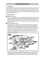
Page 17: ...adoption of a spiral drive system a mechanism using a reciprocating bearing a more compact design has been achieved by arranging the motor shaft in parallel with the tool shaft Figure 1 shows that the drill bit is pressed against the workpiece and the tool shaft is retracted The rotation of the armature is transmitted to the second shaft via the first gear The second shaft rotation is further tran...

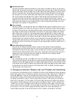
Page 18: ...ear cover is totally enclosed by oil seals O rings and other devices to prevent leakage of lubricating grease and to keep dust and dirt out of the internal mechanisms The drill bit chuck portion is protected by the rubber front cap to keep out dust and chips which could cause improper fitting of the drill bit and or other faulty operation of the chuck portion The speed control switch is also a ful...

Page 19: ... or damaged Salespersons should carefully ensure that the buyer is thoroughly advised on this point 5 Drill bits The chuck section is designed exclusively for the popular and widely available SDS plus shank bits as shown in Fig 2 Rotating torque is transmitted to the drill bit by two key rails provided in the tool holding section A steel ball is used to prevent the bit from falling out The service...

Page 20: ...y rails transmit the rotation torque To mount the bit push the bit in the tool retainer as far as it will go Pushing lightly turn the bit until it is caught At this position push the bit in as far as it will go sliding the grip is not required for mounting the bit To remove the bit slide the grip backward to the full and remove the bit Fig 4 Grip Ball holder Holder spring Steel ball Key rail 2 pcs...

Page 21: ...ll not rotate even though the tool shank continues to rotate Should the tool be operated when the dust cover is not being held against a concrete surface friction may cause dust collector B to become disconnected from the grip Accordingly caution the customer to press dust collector B and drill bit firmly against the concrete surface before tuning on the switch to start drilling When dust collecto...

Page 22: ... retaining ring puller Then the Grip 3 Ball Holder 4 Steel Ball D7 0 18 Holder Plate 5 and Holder Spring 6 can be removed from the Cylinder 19 2 Disassembly of the hammering mechanism 1 Set the Lever 12 to rotation and hammering marks Remove the Tapping Screw W Flange D4 x 30 Black 8 from the Gear Cover 7 to remove the Gear Cover 7 At this time check that the Spacer 35 at the tip of the Second Sha...

Page 23: ...it 3 Remove the First Gear 40 from the Second Shaft 36 with a bearing puller and remove the Reciprocating Bearing 38 Needle Cage 39 and Clutch 37 from the Second Shaft 36 Note that the First Gear 40 is aligned with and press fitted onto the 9 mm dia end surface of the Second Shaft 36 Components mounted on the second shaft Second Shaft 36 Piston 29 Inner Cover Ass y 33 Reciprocating Bearing 38 Rota...

Page 24: ...ed from the Cylinder 19 Insert punch A J 85 into the 4 mm dia hole 2 pcs of the Cylinder 19 and tap the Stopper Ring 2 until the Stopper Ring 2 cannot be seen from the 4 mm dia hole 2 pcs to remove the Stopper Ring 2 from the groove of the inner circumference of the Cylinder 19 Then pull out the Stopper Ring 2 from the inner circumference of the Cylinder 19 with a retaining ring puller B J 341 bei...

Page 25: ... Set 59 can be removed When disassembling the motor section be careful that Washer A 49 is mounted between the Ball Bearing 609DDC3PS2 L 48 and the Armature 50 and Washer A 52 between the Armature 50 and the Ball Bearing 626VVC2PS2L 53 Removal of the housing Disassembly of the motor section Ball Bearing 609DDC3PS2 L 48 Washer A 49 Armature 50 Washer A 52 Ball Bearing 626VVC2PS2L 53 Tapping Screw W...

Page 26: ...Steel Ball D7 0 18 to the tip of the Cylinder 19 Mount the Ball Holder 4 Grip 3 Stopper Ring 2 and Front Cap 1 Mount the Thrust Washer 26 to the Cylinder 19 Show the Lever 12 in the Gear Cover 7 and fit the Stopper 14 in the groove of the Lever 12 then push the Lever 12 in the Gear Cover 7 hard Secure the Lever 12 to the Gear Cover 7 with the Machine Screw M4 x 5 15 When assembling the component p...

Page 27: ...ection When reassembling the motor section be careful that Washer A 49 is mounted between the Ball Bearing 609DDC3PS2 L 48 and the Armature 50 and Washer A 52 between the Armature 50 and the Ball Bearing 626VVC2PS2L 53 Be sure to mount Washers A 49 and 52 facing their convex sides to the ball bearings Reassembly of the motor section A B B portion detail Face the convex sides to the ball bearings W...

Page 28: ... Blue DC Speed Control Switch 61 Lead wire RED Lead wire Black 6 Reassembly of the switch section Perform wiring properly according to the following wiring diagram when replacing the Brush Block 54 DC Speed Control Switch 61 and Battery Terminal Ass y 63 Wiring Diagram A Lead wire Red A ...

Page 29: ...e Brush Block 54 DC Speed Control Switch 61 and Battery Terminal Ass y 63 to Housing A B Set 59 as shown in the following figure being careful not to pinch the lead wires between housing A and housing B Assembly drawing of the housing Brush Block 54 Battery Terminal Ass y 63 ...

Page 30: ...rocating Bearing 38 First Gear 40 Washer B D12 5 41 8 Mounting the piston Mount the Piston 29 as shown in the figure below At this time mount the Thrust Plate 27 aligning the change lever pocket of the Inner Cover Ass y 33 with the notch of the Thrust Plate 27 Mounting direction of the thrust plate Change lever pocket Inner Cover Ass y 33 Thrust Plate 27 Notch ...

Page 31: ...claw portion inner circumference and arm portion of the Reciprocating Bearing 38 and O ring 1AP 10 13 of the Lever 12 Fill 30 g of special grease in the Gear Cover 7 and 10 g in the groove of the Inner Cover Ass y 33 Apply Hitachi Motor Grease No 29 to the Steel Ball D7 0 18 Apply 0 2 g of Hitachi Motor Grease No 29 to the sliding surfaces of Housing A B Set 59 and Lever B 62 Tapping Screw W Flang...

Page 32: ...diagram Brush Block 54 Lead wire Black Lead wire Red Battery Terminal Ass y 63 Lead wire Red Lead wire Black Lead wire Blue Lead wire Brown Battery Terminal Ass y 63 DC Speed Control Switch 61 Wiring arrangement ...

Page 33: ...Refer to the Technical Data and Service Manual for precautions in disassembly and reassembly of the battery charger Models UC 18YRL and UC 18YG BATTERY TERMINAL ASS Y CONTROL UNIT REVERSING UNIT Lead wire Brown Lead wire Blue Lead wire Red Lead wire Black DC Speed Control Switch 61 ...

Page 34: ...ing 609DD Magnet Ball Bearing 626VV Brush Block Lever O ring 1AP 10 Stopper Striker O ring A Thrust Washer Thrust Plate Spring B Piston O ring D61 Piston Pin Washer A Needle Bearing Housing A B Set Inner Cover Ass y Second Shaft Clutch Reciprocating Bearing Needle Cage First Gear Ball Bearing 626VV Second Hammer O ring B O ring P 15 Hammer Holder Gear Cover Cylinder Second Gear Spring A STANDARD R...

Page 35: ...DH 14DL 2007 7 23 E1 Hitachi Power Tools 1 2 3 4 5 6 7 8 9 10 11 14 13 12 15 16 17 18 19 20 21 22 23 2 24 25 26 27 28 29 30 31 32 34 35 36 37 38 39 40 41 42 43 45 44 46 47 48 49 50 51 52 53 501 502 503 33 54 55 56 57 64 59 67 63 68 71 504 72 70 61 60 58 69 65 66 58 62 ...

Page 36: ...21 301 672 O RING B 1 22 311 814 O RING P 15 1 23 327 878 HAMMER HOLDER 1 24 325 601 STRIKER 1 25 306 326 O RING A 1 26 327 880 THRUST WASHER 1 27 325 588 THRUST PLATE 1 28 306 976 SPRING B 1 29 306 324 PISTON 1 30 321 007 WASHER A 1 31 325 583 O RING I D D61 1 32 306 328 NEEDLE BEARING 1 33 328 479 INNER COVER ASS Y 1 INCLUD 32 43 45 34 306 322 PISTON PIN 1 35 325 587 SPACER 1 36 327 871 SECOND S...

Page 37: ...D4X20 BLACK 7 59 328 491 HOUSING A B SET 1 60 322 853 PUSHING BUTTON 1 61 328 484 DC SPEED CONTROL SWITCH 1 62 328 480 LEVER B 1 63 328 490 BATTERY TERMINAL ASS Y 1 64 HITACHI LABEL 1 65 321 918 HOOK ASS Y W LIGHT 1 INCLUD 66 68 66 321 672 TAPPING SCREW D2X6 2 67 326 276 LEVER A 1 68 320 288 V LOCK NUT M5 1 69 306 952 STRAP BLACK 1 70 319 926 HOOK SPRING 1 71 320 881 SPECIAL SCREW A M5 1 72 326 82...

Page 38: ... 971 803 ANCHOR SETTING ADAPTER B W5 8 MANUAL 1 625 944 477 COTTER 1 626 303 617 TAPER SHANK ADAPTER SDS PLUS NO 1 1 627 303 619 A TAPER SHANK ADAPTER SDS PLUS 1 628 303 620 B TAPER SHANK ADAPTER SDS PLUS 1 629 303 624 CHUCK ADAPTER D SDS PLUS 1 630 302 976 ANCHOR SETTING ADAPTER A SDS W1 4X260L 1 631 302 975 ANCHOR SETTING ADAPTER A SDS W5 16X260L 1 632 303 621 ANCHOR SETTING ADAPTER A SDS W3 8X1...

Page 39: ...DH 14DMR 2007 7 23 E1 Hitachi Power Tools 69 65 66 58 1 2 3 4 5 6 7 8 9 10 11 14 13 12 15 16 17 18 19 20 21 22 23 2 24 25 26 27 28 29 30 31 32 34 35 36 37 38 39 40 41 42 43 45 44 46 47 48 49 50 51 52 53 501 502 503 33 54 55 56 57 64 59 67 62 68 71 504 72 70 61 60 58 63 ...

Page 40: ... 21 301 672 O RING B 1 22 311 814 O RING P 15 1 23 327 878 HAMMER HOLDER 1 24 325 601 STRIKER 1 25 306 326 O RING A 1 26 327 880 THRUST WASHER 1 27 325 588 THRUST PLATE 1 28 306 976 SPRING B 1 29 306 324 PISTON 1 30 321 007 WASHER A 1 31 325 583 O RING I D D61 1 32 306 328 NEEDLE BEARING 1 33 328 479 INNER COVER ASS Y 1 INCLUD 32 43 45 34 306 322 PISTON PIN 1 35 325 587 SPACER 1 36 327 871 SECOND ...

Page 41: ...3 TAPPING SCREW W FLANGE D4X20 BLACK 7 59 328 491 HOUSING A B SET 1 60 322 853 PUSHING BUTTON 1 61 328 484 DC SPEED CONTROL SWITCH 1 62 328 480 LEVER B 1 63 328 490 BATTERY TERMINAL ASS Y 1 64 HITACHI LABEL 1 65 321 918 HOOK ASS Y W LIGHT 1 INCLUD 66 68 66 321 672 TAPPING SCREW D2X6 2 67 326 276 LEVER A 1 68 320 288 V LOCK NUT M5 1 69 306 952 STRAP BLACK 1 70 319 926 HOOK SPRING 1 71 320 881 SPECI...

Page 42: ...APTER B W1 2 MANUAL 1 624 971 803 ANCHOR SETTING ADAPTER B W5 8 MANUAL 1 625 944 477 COTTER 1 626 303 617 TAPER SHANK ADAPTER SDS PLUS NO 1 1 627 303 619 A TAPER SHANK ADAPTER SDS PLUS 1 628 303 620 B TAPER SHANK ADAPTER SDS PLUS 1 629 303 624 CHUCK ADAPTER D SDS PLUS 1 630 302 976 ANCHOR SETTING ADAPTER A SDS W1 4X260L 1 631 302 975 ANCHOR SETTING ADAPTER A SDS W5 16X260L 1 632 303 621 ANCHOR SET...

Page 43: ...DH 18DL 2007 7 23 E1 Hitachi Power Tools 1 2 3 4 5 6 7 8 9 10 11 14 13 12 15 16 17 18 19 20 21 22 23 2 24 25 26 27 28 29 30 31 32 34 35 36 37 38 39 40 41 42 43 45 44 46 47 48 49 50 51 52 53 501 502 503 33 54 55 56 57 64 59 67 62 68 71 504 72 70 61 60 58 69 65 66 58 63 ...

Page 44: ... 21 301 672 O RING B 1 22 311 814 O RING P 15 1 23 327 878 HAMMER HOLDER 1 24 325 601 STRIKER 1 25 306 326 O RING A 1 26 327 880 THRUST WASHER 1 27 325 588 THRUST PLATE 1 28 306 976 SPRING B 1 29 306 324 PISTON 1 30 321 007 WASHER A 1 31 325 583 O RING I D D61 1 32 306 328 NEEDLE BEARING 1 33 328 479 INNER COVER ASS Y 1 INCLUD 32 43 45 34 306 322 PISTON PIN 1 35 325 587 SPACER 1 36 327 871 SECOND ...

Page 45: ...D4X20 BLACK 7 59 328 492 HOUSING A B SET 1 60 322 853 PUSHING BUTTON 1 61 328 484 DC SPEED CONTROL SWITCH 1 62 328 480 LEVER B 1 63 328 490 BATTERY TERMINAL ASS Y 1 64 HITACHI LABEL 1 65 321 918 HOOK ASS Y W LIGHT 1 INCLUD 66 68 66 321 672 TAPPING SCREW D2X6 2 67 326 276 LEVER A 1 68 320 288 V LOCK NUT M5 1 69 306 952 STRAP BLACK 1 70 319 926 HOOK SPRING 1 71 320 881 SPECIAL SCREW A M5 1 72 326 24...

Page 46: ...APTER B W1 2 MANUAL 1 624 971 803 ANCHOR SETTING ADAPTER B W5 8 MANUAL 1 625 944 477 COTTER 1 626 303 617 TAPER SHANK ADAPTER SDS PLUS NO 1 1 627 303 619 A TAPER SHANK ADAPTER SDS PLUS 1 628 303 620 B TAPER SHANK ADAPTER SDS PLUS 1 629 303 624 CHUCK ADAPTER D SDS PLUS 1 630 302 976 ANCHOR SETTING ADAPTER A SDS W1 4X260L 1 631 302 975 ANCHOR SETTING ADAPTER A SDS W5 16X260L 1 632 303 621 ANCHOR SET...

Page 47: ...DH 18DMR 2007 7 23 E1 Hitachi Power Tools 69 65 66 58 1 2 3 4 5 6 7 8 9 10 11 14 13 12 15 16 17 18 19 20 21 22 23 2 24 25 26 27 28 29 30 31 32 34 35 36 37 38 39 40 41 42 43 45 44 46 47 48 49 50 51 52 53 501 502 503 33 54 55 56 57 64 59 67 62 68 71 504 72 70 61 60 58 63 ...

Page 48: ...1 21 301 672 O RING B 1 22 311 814 O RING P 15 1 23 327 878 HAMMER HOLDER 1 24 325 601 STRIKER 1 25 306 326 O RING A 1 26 327 880 THRUST WASHER 1 27 325 588 THRUST PLATE 1 28 306 976 SPRING B 1 29 306 324 PISTON 1 30 321 007 WASHER A 1 31 325 583 O RING I D D61 1 32 306 328 NEEDLE BEARING 1 33 328 479 INNER COVER ASS Y 1 INCLUD 32 43 45 34 306 322 PISTON PIN 1 35 325 587 SPACER 1 36 327 871 SECOND...

Page 49: ...PING SCREW W FLANGE D4X20 BLACK 7 59 328 492 HOUSING A B SET 1 60 322 853 PUSHING BUTTON 1 61 328 484 DC SPEED CONTROL SWITCH 1 62 328 480 LEVER B 1 63 328 490 BATTERY TERMINAL ASS Y 1 64 HITACHI LABEL 1 65 321 918 HOOK ASS Y W LIGHT 1 INCLUD 66 68 66 321 672 TAPPING SCREW D2X6 2 67 326 276 LEVER A 1 68 320 288 V LOCK NUT M5 1 69 306 952 STRAP BLACK 1 70 319 926 HOOK SPRING 1 71 320 881 SPECIAL SC...

Page 50: ...APTER B W1 2 MANUAL 1 624 971 803 ANCHOR SETTING ADAPTER B W5 8 MANUAL 1 625 944 477 COTTER 1 626 303 617 TAPER SHANK ADAPTER SDS PLUS NO 1 1 627 303 619 A TAPER SHANK ADAPTER SDS PLUS 1 628 303 620 B TAPER SHANK ADAPTER SDS PLUS 1 629 303 624 CHUCK ADAPTER D SDS PLUS 1 630 302 976 ANCHOR SETTING ADAPTER A SDS W1 4X260L 1 631 302 975 ANCHOR SETTING ADAPTER A SDS W5 16X260L 1 632 303 621 ANCHOR SET...

Reviews: