19
Be sure to remove the storage batteries from the main body before servicing. Inadvertent triggering of the
switch with the storage battery connected will result in danger of accidental turning of the motor.
1. Precautions in Disassembly and Reassembly
The
[Bold]
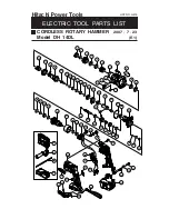
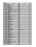
numbers in the description below correspond to the item numbers in the Parts List and the
exploded assembly diagram for the Models DH 14DL, DH 14DMR, DH 18DL and DH 18DMR.
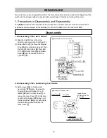
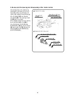
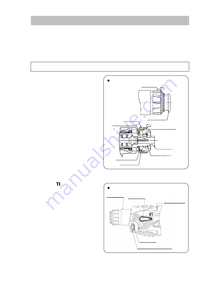
1. Disassembly of the tool retainer
(1) Slide the Grip
[3]
fully in the arrow
direction and remove the Front Cap
[1]
.
(2) Pulling the Grip
[3]
, remove the Stopper
Ring
[2]
with a retaining ring puller. Then
the Grip
[3]
, Ball Holder
[4]
, Steel Ball
D7.0
[18]
, Holder Plate
[5]
and Holder
Spring
[6]
can be removed from the
Cylinder
[19]
.
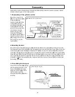
2. Disassembly of the hammering mechanism
(1) Set the Lever
[12]
to “rotation and
hammering” (
marks). Remove the
Tapping Screw (W/Flange) D4 x 30
(Black)
[8]
from the Gear Cover
[7]
to
remove the Gear Cover
[7]
. At this time,
check that the Spacer
[35]
at the tip of
the Second Shaft
[36]
is not adhered to
the ball bearing press-fitted into the
Gear Cover
[7]
.
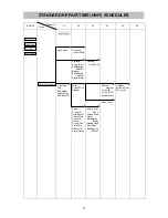
REPAIR GUIDE
Disassembly of the tool retainer
Front Cap
[1]
Grip
[3]
Holder Spring
[6]
Ball Holder
[4]
Holder Plate
[5]
Stopper Ring
[2]
Grip
[3]
Cylinder
[19]
Steel Ball D7.0
[18]
Disassembly
Removal of the gear cover
Gear Cover
[7]
Tapping Screw
(W/Flange) D4 x 30
(Black)
[8]
Spacer
[35]
Ball bearing press-fitted
into the Gear Cover
[7]
Lever
[12]


