−
2
−
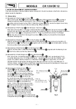
1-2. Reassembly:
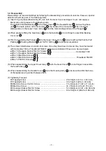
Reassembly can be accomplished by following the disassembly procedures in reverse. However, special
attention should be given to the following items.
(1) Insert 30 g of grease (Molub-Alloy #1) into both the Gear Cover and Upper Cover. Also apply a
liberal amount of grease to the following parts:
The 6202VVCM Ball Bearing
24
in the Gear Cover
26
, the Neelde Roller
17
, Connecting Piece
(A)
16
, the teeth portion of the Gear Ass’y
21
, the inside of the Connector
14
, the Connector
sliding portion in the Upper Cover Ass’y
11
, and the metal sliding portion of the Plunger
5
.
(2) When pressure fitting the Gear Ass’y
21
onto the Spindle
25
, do not forget to assemble Bearing
Cover (A)
23
.
(3) Prior to reinstalling the Plunger
5
into the Upper Cover Ass’y
11
, ensure without fail that the Felt
Packing
7
, Packing Washer
6
and 1AP12 O-Ring
8
are properly assembled.
(4) The screws listed below are seal lock screws. Once they have been removed, they must be treated
with Cemedine 1500 or ThreeBond TB2410 adhesive as indicated if they are to be used again.
z
#
M6 x 16 Hexagon Socket Flat Hd. Screws
18
z
#
M5 x 12 Hexagon Socket Flat Hd. Screws
15
z
#
M5 x 16 Machine Screws
10
z
#
M4 x 12 Machine Screws
44
..................................................................... ThreeBond TB2410
z
#
M4 x 12 Flat Hd. Screws
22
(5) When reassembling the Upper Cover Ass’y
11
onto the Gear Cover
26
, do not forget to assemble
the Seal Packing
12
.
(6) When reassembling the Handle Cover
56
onto the Housing Ass’y
42
, ensure without fail that none
of the leadwires are pinched between them.
(7) Tightening Torques:
D4 Tapping Screw ........................................................................... 20 ± 5kgf-cm (17.4 ± 4.34 in-lb)
D5 Tapping Screw ........................................................................... 30 ± 5kgf-cm (26 ± 4.34 in-lb)
M4 Machine Screw, Flat Hd. Screw ................................................ 15 - 20kgf-cm (13.02 ± 17.4 in-lb)
M5 Machine Screw .......................................................................... 30 - 55kgf-cm (26 ± 47.75 in-lb)
M5 Hexagon Socket Flat Hd. Screw ................................................ 50 - 60kgf-cm (43.41 ± 52.09 in-lb)
M6 Hexagon Socket Flat Hd. Screw ................................................ 80 ± 10kgf-cm (69.45 ± 8.68 in-lb)
11111111111111111111111111111111111111111111
Cemedine 1500
Summary of Contents for CR12
Page 1: ......


