


--- 18 ---
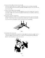
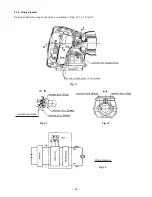
(2) Reinstallation of the spindle and gear section to the Gear Cover Ass'y
[27]
Insert the Spindle
[23]
into the Ball Bearing 6901ZZCMPS2L
[22]
, Bearing Cover (B)
[21]
, Gear
[37]
and
Balance Weight
[36]
in order. Secure the spindle and gear section secured with the Nylock Hex. Socket Flat
Hd. Bolt M6 x 16
[29]
to the Gear Cover Ass'y
[27]
with the three Seal Lock Flat Hd. Screws M4 x 12
[20]
aligning the holes of the Balance Weight
[36]
with the holes of Bearing Cover (B)
[21]
and the screw holes of
the Gear Cover Ass'y
[27]
. If the first Seal Lock Flat Hd. Screw M4 x 12
[20]
is tightened firmly, the other two
Seal Lock Flat Hd. Screws M4 x 12
[20]
cannot be aligned. Lightly tighten the first Seal Lock Flat Hd. Screw
M4 x 12
[20]
.
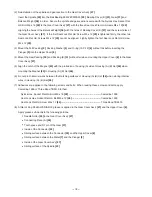
(3) Mount the Felt Packing
[5]
, Packing Washer
[4]
and O-ring (1AP-12)
[6]
without fail before inserting the
Plunger
[3]
into the Upper Cover
[8]
.
(4) Mount the Seal Packing
[30]
and Packing (B)
[31]
without fail when mounting the Upper Cover
[8]
to the Gear
Cover Ass'y
[27]
.
(5) Align the notch of the Magnet
[43]
with the protrusion of housing (A) side of Housing (A).(B) Set
[46]
when
mounting the Magnet
[43]
to Housing (A).(B) Set
[46]
.
(6) Do not pinch internal wires between the matching surfaces of Housing (A).(B) Set
[46]
when storing internal
wires in Housing (A). (B) Set
[46]
.
(7) Adhesives are applied to the following screws and bolts. When reusing these screws and bolts, apply
Cemedine 1500 or Three Bond TB2410 to them.
Nylock Hex. Socket Flat Hd. Bolt M6 x 16
[29] .................................................
Cemedine 1500
Seal Lock Hex. Socket Flat Hd. Bolt M5 x 12
[28] ............................................
Cemedine 1500
Seal Lock Flat Hd. Screw M4 x 12
[20] .............................................................
Three Bond TB2410
(8) A total of 35 g Shell ALVANIA RL3 grease is applied in the Gear Cover Ass'y
[27]
and the Upper Cover
[8]
.
Apply grease sufficiently to the following portions:
Needle Roller
[35]
in the Gear Cover Ass'y
[27]
Connecting Piece (A)
[34]
Tooth space and D7 pin of the Gear
[37]
Inside of the Connector
[33]
Sliding surface between the Connector
[33]
and the Upper Cover
[8]
Sliding surface between the Metal
[7]
and the Plunger
[3]
Inside of the Gear Cover Ass'y
[27]
Sliding surface of the Spindle
[23]
Summary of Contents for CR 18DMR
Page 29: ......


