background image

INTER

INPUT

M1-D

RGB

BNG

S-VIDEO

STANDBY/ON

TEMP

VIDEO

COMPONENT

LAMP

KEYSTONE

SEARCH

RESET

MENU

FOCUS

LENS SHIFT

ZOOM

  VIDEO

R-AUDIO IN-L

S-VIDEO

BNC

RGB

AUDIO IN1

AUDIO IN2

RGB OUT

AUDIO OUT

REMOTE CONTR

OL

R/CR/PR

G/Y

B/CB/PB

H

V

Y

 CONTROL

 NETWORK

CR/PR Ca/Pa

11

Setting Up (continued)

Setting Up (continued)

REMOTE CONTROL

  VIDEO

R-AUDIO IN-L

S-VIDEO

BNC

RGB

AUDIO IN1

AUDIO IN2

RGB OUT

AUDIO OUT

R/C

R

/P

R

G/Y

B/C

B

/P

B

H

V

Y

 CONTROL

 NETWORK

CR/PR Ca/Pa

L

REMOTE CONTROL

  VIDEO

R-AUDIO IN-L

S-VIDEO

BNC

RGB

AUDIO IN1

AUDIO IN2

RGB OUT

AUDIO OUT

R/C

R

/P

R

G/Y

B/C

B

/P

B

H

V

Y

 CONTROL

 NETWORK

CR/PR Ca/Pa

M

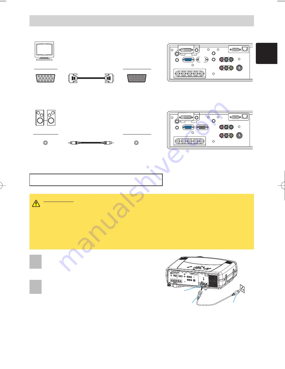
Monitor

Projector

RGB in

RGB cable

RGB OUT

Connecting to a monitor

Speaker

Projector

Connecting to a speaker (with amplifier)

Audio in

Stereo Mini cable

AUDIO OUT

M

L

WARNING

• Use extra caution when connecting the power cord as incorrect or faulty

connections may result in fire and/or electrical shock. Please adhere to the “User’s manual –

Safety Guide” and the following. 
• Only plug the power cord into outlets rated for use with the power cord’s specified voltage range.
• Only use the power cord that came with the projector. If it is damaged, contact your dealer to

newly get correct one.

• Never modify the power cord. Never attempt to defeat the ground connection of the three-pronged plug.
• Make sure that you firmly connect the power cord to the projector and wall outlet.

1

Connect the connector of the power cord to
the AC inlet of the projector.

2

Firmly plug the power cord’s plug into the
outlet.

AC Inlet

Connector

Plug

Outlet

Connecting The Power Supply

01CP-X1200-ENG-OG-三校  03.12.5  1:10 PM  ページ11

Summary of Contents for CP-X1200 Series

Page 1: ...Portable LCD Projector ...

Page 2: ...be disconnected from the power outlet WARNING This symbol indicates information that if ignored could possibly result in personal injury or even death due to incorrect handling CAUTION This symbol indicates information that if ignored could result possibly in personal injury or physical damage due to incorrect handling Thank you for purchasing this projector The information in this manual is subje...

Page 3: ...cosmetics liquids such as water etc on or around the projector Do not place metals combustibles etc on or around the projector To avoid penetration of foreign objects do not put the projector into a case or bag together with any thing except the accessories of the projector signal cables and connectors Never disassemble and modify The projector contains high voltage components Modification and or ...

Page 4: ...t vision Use special caution in households where children are present Use only the correct power cord and the correct power outlet Incorrect power supply could result in fire or electrical shock Use only the correct power outlet depending on the indication on the projector and the safety standard The enclosed power cord must be used depending on the power outlet to be used Be cautious of the power...

Page 5: ...onnecting the power cord or cables do it with your hand holding the plug or connector Do not place the cord near the heater Avoid bending the power cord sharply Do not attempt to work on the power cord Be careful in handling the battery of the remote control Incorrect handling of the battery could result in fire or personal injury The battery may explode if not handled properly Keep the battery aw...

Page 6: ...e The air filter should be cleaned periodically If the air filter becomes clogged by dust or the like internal temperature rises and could cause malfunction The projector may display the message such as CHECK THE AIR FLOW or turn off the projector to prevent the internal heat level rising When the indicators or a message prompts you to clean the air filter clean the air filter as soon as possible ...

Page 7: ...ces or abrasive cleaner Before using chemical wipes be sure to read and observe the instructions Do not allow long term close contact with rubber or vinyl About bright spots or dark spots Although bright spots or dark spots may appear on the screen this is a unique characteristic of liquid crystal displays and such do not constitute or imply a machine defect Be careful of printing of the LCD panel...

Page 8: ...RT Do not use a polarized screen It can cause red image Turn the power on off in right order To prevent any trouble turn on off the projector in right order mentioned below unless specifying Power on the projector before the computer or video tape recorder Power off the projector after the computer or video tape recorder Take care not to fatigue your eyes Rest the eyes periodically Set the sound v...

Page 9: ...r get it in your eyes or mouth Before replacing the lamp make sure the power switch is off and the power cable is not plugged in then wait at least 45 minutes for the lamp to cool sufficiently Handling the lamp while hot can cause burns as well as damaging the lamp Do not open the lamp cover while the projector is suspended from above This is dangerous since if the lamp s bulb has broken the shard...

Page 10: ...utlet on a circuit different from that to which the receiver is connected Consult the dealer or an experienced radio TV technician for help INSTRUCTIONS TO USERS This equipment complies with the requirements of FCC Federal Communication Commission equipment provided that the following conditions are met Some cables have to be used with the core set Use the accessory cable or a designated type cabl...

Page 11: ...control 7 Batteries for the remote control 8 User s Manuals Safety Guide Quick Guide Operating Guide INTER INPUT M1 D RGB BNG S VIDEO STANDBY ON TEMP VIDEO COMPONENT LAMP KEYSTONE SEARCH RESET MENU FOCUS LENS SHIFT ZOOM STANDBY ON VIDEO LASER INDICATOR ESC MENU POSITION RESET AUTO KEYSTONE 1 2 3 ID CHANGE SEARCH ON OFF FREEZE MUTE MAGNFY PinP VOLUME RGB BLANK PREVIOUS NEXT ASPECT ENTER LASER LENS ...

Page 12: ...N L S VIDEO BNC RGB AUDIO IN1 AUDIO IN2 RGB OUT AUDIO OUT REMOTE CONTROL R CR PR G Y B CB PB H V Y CONTROL NETWORK CR PR Ca Pa A E F G REMOTE CONTROL VIDEO R AUDIO IN L S VIDEO BNC RGB AUDIO IN1 AUDIO IN2 RGB OUT AUDIO OUT G Y H V Y CONTROL NETWORK CR PR Ca Pa R CR PR B CB PB B D REMOTE CONTROL VIDEO R AUDIO IN L S VIDEO BNC RGB AUDIO IN1 AUDIO IN2 RGB OUT AUDIO OUT R CR PR G Y B CB PB H V Y CONTR...

Page 13: ...L NETWORK CR PR Ca Pa H J REMOTE CONTROL VIDEO R AUDIO IN L S VIDEO BNC RGB AUDIO IN1 AUDIO IN2 RGB OUT AUDIO OUT R CR PR G Y B CB PB H V Y CONTROL NETWORK CR PR Ca Pa H K Monitor Projector RGB in RGB cable RGB OUT Connecting to a monitor Speaker Projector Connecting to a speaker with amplifier Audio in Stereo Mini cable AUDIO OUT M VCR DVD Player Projector Connecting to a VCR DVD Player If using ...

Page 14: ...tempt to defeat the ground connection of the three pronged plug Make sure that you firmly connect the power cord to the projector and wall outlet 1 Connect the connector of the power cord to the AC inlet of the projector 2 Firmly plug the power cord s plug into the outlet AC Inlet Connector Plug Outlet WARNING Do not touch about the lens and ventilation openings during use or immediately after use...

Page 15: ... NFY PinP VO LU ME RGB BLANK PREVIOUS NEXT ASPECT ENTE R LASER LENS SHIFT FOCUS ZOOM 1 Remove the battery cover Slide back and remove the battery cover in the direction of the arrow Insert the batteries Align and insert the two AA batteries according to their plus minus terminals as indicated in the remote control Close the battery cover Replace the battery cover in the direction of the arrow and ...

Page 16: ...a trademark of Microsoft Corporation All other trademarks are the property of their respective owners WARNING Before using read the User s Manual Safety Guide and these manuals to ensure correct usage through understanding After reading store them in a safe place for future reference INTER INPUT M1 D RGB BNG S VIDEO STANDBY ON TEMP VIDEO COMPONENT LAMP KEYSTONE SEARCH RESET MENU FOCUS LENS SHIFT Z...

Page 17: ...correction of distorted images electrically Optical Lens Shift The lens of this projector can be shifted vertically When you want to finely adjust the picture position use the LENS SHIFT buttons This multimedia projector is used to project various computer signals as well as NTSC PAL SECAM video signals onto a screen Little space is required for installation and large images can easily be realized...

Page 18: ... The Picture Position 18 Correcting The Keystone Distortion 18 Adjusting The Volume 19 Muting The Sound 19 Temporarily Blanking The Screen 19 Freezing The Screen 20 Using The Magnify Feature 20 Displaying The Child Window 21 Selecting An Audio Input 21 Multifunctional Settings 22 Using The Menu Functions 22 MAIN Menu 23 PICTURE 1 Menu 24 PICTURE 2 Menu 26 INPUT Menu 27 AUTO Menu 29 SCREEN Menu 31 ...

Page 19: ...t 7 REMOTE CONTROL port 8 DC OUT port 9 AC Inlet 0 Power switch Control buttons See the following page Projector Front Right Projector Rear Left INTER INPUT M1 D RGB BNG S VIDEO STANDB Y ON TEMP VIDEO COMPON ENT LAMP KEYSTO NE SEARCH RESET MENU FOCUS LENS SHIFT ZOOM 1 2 3 5 4 6 INTER INPUT M1 D RGB BNG S VIDEO STANDBY ON TEMP VIDEO COMPONENT LAMP KEYSTONE SEARCH RESET MENU FOCUS LENS SHIFT ZOOM VI...

Page 20: ...cator 3 LAMP indicator 4 LENS SHIFT buttons 5 INPUT dial 6 SEARCH button 7 M1 D indicator 8 RGB indicator 9 BNC indicator 0 COMPONENT indicator S VIDEO indicator VIDEO indicator q ZOOM buttons w FOCUS buttons e KEYSTONE button r MENU button t RESET button y ENTER button u Cursor buttons Control Panel on the Projector Remote Control i LASER INDICATOR o VIDEO button p RGB button BLANK button ASPECT ...

Page 21: ...44 3 7 24 61 48 122 100 2 5 120 3 0 181 4 6 30 76 60 152 120 3 0 144 3 7 217 5 5 36 91 72 183 150 3 8 181 4 6 272 6 9 45 114 90 229 200 5 1 243 6 2 364 9 2 60 152 120 305 250 6 4 304 7 7 455 11 6 75 191 150 381 300 7 6 366 9 3 547 13 9 90 229 180 457 350 8 9 427 10 9 638 16 2 105 267 210 533 400 10 2 489 12 4 730 18 5 120 305 240 610 500 12 7 612 15 5 913 23 2 150 381 300 762 Screen Size inch m a ...

Page 22: ...mmediately after use to prevent a burn CAUTION To prevent damaging the projector and injuring yourself always hold the projector whenever using the elevator buttons to adjust the elevator feet Press and hold in the elevator buttons Raise or lower the projector to the desired height and then release the elevator buttons When you release the elevator buttons the elevator feet will lock into position...

Page 23: ... external image output set the laptop to CRT display or to simultaneous LCD and CRT display For details on how this is done please refer to the instruction manual of the corresponding laptop computer Some computers may have multiple display screen modes Use of some of these modes may not be compatible with this projector For some RGB input modes the optional Mac adapter is necessary When the image...

Page 24: ...AUDIO OUT REMOTE CONTROL R CR PR G Y B CB PB H V Y CONTROL NETWORK CR PR Ca Pa A E F G REMOTE CONTROL VIDEO R AUDIO IN L S VIDEO BNC RGB AUDIO IN1 AUDIO IN2 RGB OUT AUDIO OUT G Y H V Y CONTROL NETWORK CR PR Ca Pa R CR PR B CB PB B D REMOTE CONTROL VIDEO R AUDIO IN L S VIDEO BNC RGB AUDIO IN1 AUDIO IN2 RGB OUT AUDIO OUT R CR PR G Y B CB PB H V Y CONTROL NETWORK CR PR Ca Pa C D Computer Projector RG...

Page 25: ...ector If using a s video signal If using a component signal R AUDIO IN L VIDEO R AUDIO IN L VIDEO COMPONENT S video out S video cable S VIDEO J CR PR CB PB Y CR PR out CB PB out Y out R AUDIO IN L VIDEO R AUDIO IN AUDIO IN L Audio out R Audio out L Audio out R Audio out L R AUDIO IN AUDIO IN L R AUDIO IN AUDIO IN L VIDEO IN Audio out R Audio out L Video out H H K H REMOTE CONTROL VIDEO R AUDIO IN ...

Page 26: ... Projector Connecting to a speaker with amplifier Audio in Stereo Mini cable AUDIO OUT M L WARNING Use extra caution when connecting the power cord as incorrect or faulty connections may result in fire and or electrical shock Please adhere to the User s manual Safety Guide and the following Only plug the power cord into outlets rated for use with the power cord s specified voltage range Only use t...

Page 27: ...ets Use only the battery specified two AA batteries Do not mix new battery with used one Make sure the plus and minus terminals are correctly aligned when loading the battery as indicated in the remote control Dispose of batteries in accord with environmental laws 1 Remove the battery cover Slide back and remove the battery cover in the direction of the arrow Insert the batteries Align and insert ...

Page 28: ...screen etc may be available If it is difficult to send a remote signal to the sensor directly please try Since the remote control uses infrared light to send signals to the projector Class1 LED be sure to use the remote control in an area free from obstacles that could block the remote control s output signal to the projector memo You can use the remote control as a wired remote control by connect...

Page 29: ... Using the USB control feature you can use the remote control as a simplified mouse or keyboard of the computer Connect the M1 D port of the projector to the computer via the M1 D cable Then functions illustrated below will be enabled memo The USB control can be used with Windows 95 OSR 2 1 or higher It may not be possible to use the remote control depending on the computer s configurations and mo...

Page 30: ...evices Power off the projector after the connected devices NOTE Power ON OFF Power ON OFF Remove the lens cap 2 Set the power switch to ON The STANDBY ON indicator will light to solid orange STANDBY ON STANDBY ON button indicator LENS SHIFT buttons Power switch ON position STANDBY ON button STANDBY ON 3 Press the STANDBY ON button The projector lamp will light up and the STANDBY ON indicator will ...

Page 31: ...IO IN1 AUDIO IN2 RGB OUT AUDIO OUT REMOTE CONTROL R CR PR G Y B CB PB H V Y CONTROL NETWORK CR PR Ca Pa ENTER INPUT M1 D RGB BNC S VIDEO VIDEO COMPONENT SEARCH RESET MENU Using the INPUT dial Press the SEARCH button of the projector or the remote control Pressing the button automatically cycles through input ports and displays the picture of retrieved signal memo If no signal is found or the proje...

Page 32: ...y adjusted Use a bright screen when adjusting The signal type mode best suited for the respective input signal will be selected automatically memo This function is available only when the AUTO is selected to the item VIDEO of the INPUT menu For a component video signal the signal type is identified automatically independently of this function Selecting The Aspect Ratio Press the Aspect button to t...

Page 33: ...e the position press the RESET button during adjustment 3 1 Press the POSITION button again to close the dialog and complete this operation memo Even if you don t do anything the dialog will automatically disappear after a few seconds 2 Use the cursor buttons to select the direction of distortion to correct or 4 Press the KEYSTONE button again to close the dialog and complete this operation memo E...

Page 34: ...t a dialog will appear on the screen to aid you in adjusting the volume Use the cursor buttons to adjust the volume Press the VOLUME button again to close the dialog and complete this operation memo Even if you don t do anything the dialog will automatically disappear after a few seconds Press the MUTE button As illustrated on the right a dialog will appear on the screen indicating that you have m...

Page 35: ...changes some display state ex blanking the screen displaying a dialog or a menu adjusting the picture changing the input signal is pressed or a button of projector is pressed If the projector continues projecting the same image for a long time i e you forget to exit FREEZE mode the image might possibly remain as an afterimage Do not leave the projector in FREEZE mode for too long NOTE Using The Ma...

Page 36: ...fer to the items P INP INPUT and P INP POSIT of the table of the section INPUT Menu Selecting An Audio Input When the child window is on the screen press the VOLUME button As illustrated on the right a dialog will appear on the screen Press the VOLUME button again to close the dialog and complete this operation memo Even if you don t do anything the dialog will automatically disappear after a few ...

Page 37: ...turn to the previous display press the or ESC button Press the MENU button again to close the menu display and complete this operation memo Even if you don t do anything the menu will automatically disappear after a few seconds 3 Select the SPEAKER using the button then press the button 4 Use the cursor button to select the TURN OFF 5 Press the MENU button 2 Select the OPTION using the button then...

Page 38: ...16 9 The NORMAL keeps the original aspect ratio of the input signal At a RGB signal not M1 D 4 3 16 9 At a video signal 4 3 16 9 SMALL memo At a HDTV signal of 1125i or 750p only the 16 9 can be selected WHISPER Select the NORMAL or the WHISPER using the buttons NORMAL WHISPER When the WHISPER is selected acoustic noise and screen brightness are reduced MIRROR Select a mirror status using the butt...

Page 39: ... Down COLOR TEMP Select a color temperature using the buttons HIGH MIDDLE LOW USER R Adjust the red color level for the USER mode of the COLOR TEMP using the buttons Strong Weak G Adjust the green color level for the USER mode of the COLOR TEMP using the buttons Strong Weak B Adjust the blue color level for the USER mode of the COLOR TEMP using the buttons Strong Weak COLOR BAL R Adjust the red co...

Page 40: ...e number corresponds with the command s number Performing the LOAD1 LOAD2 LOAD3 or LOAD4 loads the data on the memory whose number corresponds with the command s number and adjusts the picture automatically depending on the data RESET Select the EXECUTE using the button to reset the PICTURE 1 menu items EXECUTE CANCEL The items of the PICTURE 1 menu are collectively returned to the initial setting...

Page 41: ...inate flicker using the buttons Right Left memo This item can be selected only at a RGB signal or a component video signal other than a COMPONENT port input of 525i 625i SCART RGB H SIZE Adjust the horizontal size using the buttons Large Small memo This item can be selected only at a RGB signal memo When this adjustment is excessive the picture may not be displayed correctly In such a case please ...

Page 42: ...de using the buttons AUTO NTSC PAL SECAM NTSC4 43 M PAL N PAL Selecting the AUTO automatically selects the optimum mode memo This item is performs only at a video signal from the VIDEO port or the S VIDEO port For a component video signal the signal type is identified automatically independently of this function memo The AUTO operation may not work well at some signals If the picture becomes unsta...

Page 43: ...e FRAME LOCK message means the frame lock function is working This function automatically works when a RGB signal with vertical frequency of 50 to 60 is input and it displays a moving picture more smoothly memo The SCART RGB message means the COMPONENT port is working as a SCART RGB port Please refer to the item COMPONENT in this table S2 ASPECT Select the TURN ON or the TURN OFF using the buttons...

Page 44: ...tically independently of this function memo This operation requires approximately 10 seconds and the message AUTO IN PROGRESS is displayed during the operation memo This operation may not work well at some signals If the picture becomes unstable ex a irregular picture a color lack please select the suitable mode to the item VIDEO of the INPUT menu POWER OFF Set the time using the buttons Long max ...

Page 45: ...d pressing the RGB button selects the M1 D ports and pressing the VIDEO button selects the COMPONENT port memo If no signal is found or the projector is unstable to find an input signal at any of its ports it will return to the state it was in prior to the search RESET Select the EXECUTE using the button to reset the AUTO menu items EXECUTE CANCEL The items of the AUTO menu are collectively return...

Page 46: ...ng the buttons MyScreen ORIGINAL TURN OFF The START UP screen is the screen which is displayed by detecting no signal or an unsuitable signal The MyScreen is the screen you can register a desired screen and the ORIGINAL is the existing standard screen When the TURN OFF is selected the BLUE is used memo To avoid remaining as an afterimage the MyScreen and the ORIGINAL screens will change to the BLA...

Page 47: ...ing SCREEN Menu continued How to register your picture as the MyScreen MyScreen is pointed on the SCREEN menu The MyScreen menu appears Do you capture the picture from the current screen Registering It takes about 1 minute to register Just when the picture registration is completed the registered screen and the message of the right is displayed for a few seconds If the picture registration failed ...

Page 48: ...or is controlled by a remote control irrespective of the position of the ID CHANGE switch memo Please refer to the section Using The Remote ID Feature LAMP TIME Pressing the RESET button for about 3 seconds displays the LAMP TIME menu Select the RESET using button to reset the timer RESET CANCEL Selecting the RESET resets the count of the lamp timer to 0 memo Perform this function only when you ha...

Page 49: ... H POSITION the clock phase H PHASE and the horizontal size H SIZE LENS TYPE Select the lens type currently used using the buttons AUTO 1 2 3 4 5 Please select depending on the following AUTO automatically selects optimum mode 1 for a standard lens Type NL 500 etc 2 for a fixed short throw lens Type FL 501 etc 3 for a short throw lens Type SL 502 etc 4 for a long throw lens Type LL 503 etc 5 for a...

Page 50: ... the SUBNET MASK menu The SUBNET MASK is an address of the Network 2 Set the same number as the address of the Network to be used Pressing the or the ENTER button at the SUBNET MASK menu calls the DEFAULT GATEWAY menu The DEFAULT GATEWAY is the address of the main device 3 Set the same number as the address of the device as gateway to an outer Network DHCP Select the TURN ON or the TURN OFF using ...

Page 51: ...you use a Network suitable to the DHCP function or has been set up You can set the IP Address the Subnet Mask the Gateway and the DHCP on off using a Web Browser of the computer connected to the Network Although it needs a Web Browser of Internet Explorer 4 0 or higher Input the same IP address as set to the projector to the Web Browser of the computer connected to LAN ex Case of IP Address 192 16...

Page 52: ... get it in your eyes or mouth Before replacing the lamp make sure the power switch is off and the power cable is not plugged in then wait at least 45 minutes for the lamp to cool sufficiently Handling the lamp while hot can cause burns as well as damaging the lamp Do not open the lamp cover while the projector is suspended from above This is dangerous since if the lamp s bulb has broken the shards...

Page 53: ... sure that the lamp cover does t come up 7 Turn on the projector and reset the lamp timer 1 While the projector running press the MENU button to open the menu 2 Choose the OPTION on the menu using the button then press the button or ENTER button 3 Choose the LAMP TIME using the button then press and hold the RESET button for 3 seconds 4 Choose the RESET using the button memo When the lamp has been...

Page 54: ...acuum cleaner to the top of the filter cover and the air filter to clean If the soiling will not come off the air filter or it becomes damaged it needs to be replaced If the air filter needs to be replaced contact your dealer to prepare a new air filter Tell the dealer your air filter type Turn on the projector power and reset the filter timer 1 While the projector running press the MENU button to...

Page 55: ...zene and paint thinner Do not use aerosols or sprays Do not polish or wipe with hard objects Caring For The Inside Of The Projector In order to ensure the safe use of your projector please have it cleaned and inspected by your local dealer about once every 2 years Turn off the projector and unplug the power cord Lightly wipe the lens with a commercially available lens cleaning wipe Do not touch th...

Page 56: ...prior to the functioning of the automatic shut down function of this projector NOTE This table is continued to the following page Message Description CHANGE THE LAMP AFTER REPLACING LAMP RESET THE LAMP TIMER The time the lamp timer has counted is approaching 2000 hours Preparation of a new lamp and an early lamp change is recommended After you have change the lamp please be sure to reset the lamp ...

Page 57: ...ure is rising Please turn the power OFF and allow the unit to cool down at least 20 minutes After the projector has sufficiently cooled down please make confirmation of the following items and then turn the power on again Is there blockage of the air passage aperture Is the air filter dirty Does the peripheral temperature exceed 35 C NO INPUT IS DETECTED ON There is no input signal Please confirm ...

Page 58: ...ndby state Please refer to the section Power On Off Blinking in Green Turned off Turned off The projector is warming up Please wait Lighting in Green Turned off Turned off The projector is in an on state Ordinary operations may be performed Blinking in Orange Turned off Turned off The projector is cooling down Please wait Blinking in Red discre tionary discre tionary The projector is cooling down ...

Page 59: ...d after the treatment please contact your dealer or service company Lighting in Red Turned off Lighting in Red There is a possibility that the interior portion has become heated Please turn the power off and allow the unit to cool down at least 20 minutes After the projector has sufficiently cooled down please make confirmation of the following items and then turn the power on again Is there block...

Page 60: ...trical power cord is not plugged in Correctly connect the power cord 11 The power switch is not set to the on position Set the power switch to On 15 The main power source has been interrupted during operation such as by a power outage blackout etc Please turn the power off and allow the unit to cool down at least 20 minutes After the projector has sufficiently cooled down please turn the power on ...

Page 61: ...nu function 23 The screen is blanked Press the BLANK button to return to the input signal screen 19 Colors have a faded out appearance or Color tone is poor Color settings are not correctly adjusted Perform picture adjustments by changing the COLOR BAL R COLOR BAL G COLOR BAL B COLOR and or TINT settings using the menu functions 24 Pictures appear dark The brightness and or contrast are adjusted t...

Page 62: ...ls 786 432 pixels 1024 horizontal x 768 vertical Lens Zoom lens F 1 7 2 4 f 30 5 45 8 mm Lamp 310W UHB Speaker 1 0W 1 0W Stereo Power supply AC100 120V 5 2A AC220 240V 2 2A Power consumption 470W Temperature range 0 35 C Operating Size 420 W x 150 H x 310 D mm Not including protruding parts Please refer to the figure of the section TECHNICAL of the end of this manual Weight mass 7 7 kg Ports Optio...

Page 63: ...ting Guide User s Manual Operating Guide TECHNICAL INTER INPUT M1 D RGB BNG S VIDEO STANDBY ON TEMP VIDEO COMPONENT LAMP KEYSTONE SEARCH RESET MENU FOCUS LENS SHIFT ZOOM Dimensions Dimensions 210 85 5 Lens shift 1 1 to 92 99 Lens shift 10 0 160 320 73 unit mm 10 0 1 1 ...

Page 64: ... sync or a sync on G NOTE Example Of Computer Signal Example Of Computer Signal Resolution H V fH kHz fV Hz Rating Signal mode Display mode 720 400 37 9 85 0 VESA TEXT Zoom in 640 480 31 5 59 9 VESA VGA 60Hz Zoom in 630 480 35 0 66 7 Mac13 mode Zoom in 640 480 37 9 72 8 VESA VGA 72Hz Zoom in 640 480 37 5 75 0 VESA VGA 75Hz Zoom in 640 480 43 3 85 0 VESA VGA 75Hz Zoom in 800 600 35 2 56 3 VESA SVGA...

Page 65: ...GA 85Hz 1 1 2 7 14 2 0 6 Mac 16 mode 1 1 3 9 14 5 0 6 XGA 60Hz 2 1 2 5 15 8 0 4 XGA 70Hz 1 8 1 9 13 7 0 3 XGA 75Hz 1 2 2 2 13 0 0 2 XGA 85Hz 1 0 2 2 10 8 0 5 1152 864 75Hz 1 2 2 4 10 7 0 6 1280 960 60Hz 1 0 2 9 11 9 0 9 1280 1024 60Hz 1 0 2 3 11 9 0 4 1280 1024 75Hz 1 1 1 8 9 5 0 2 1280 1024 85Hz 1 0 1 4 8 1 0 4 1600 1200 60Hz 1 2 1 9 9 9 0 4 Computer Signal Vertical signal timimg lines a b c d TE...

Page 66: ... M D S Data2 T M D S Data1 o T M D S Data0 2 T M D S Data2 T M D S Data1 p T M D S Data0 3 T M D S Data2 Return q T M D S Data1 Return T M D S Data0 Return 4 T M D S Clock Return w T M D S Clock USB 5V DC Input 5 e T M D S Clock DDC USB Return 6 V Sync r USB Date a DDC Date SDA 7 t USB Date s DDC Clock SCL 8 Hot Plug Detect 5V DC Output y d DDC 5V DC Input 9 u f 0 i g B M1 D C BNC R G B H V BNC ja...

Page 67: ...3 PAL60 1 0 0 1 Vp p at 75 Ω terminator K COMPONENT CR PR CB PB Y RCA jack x3 System 525i 480i 525p 480p 625i 575i 720p 1080i 1035i Y signal 1 0 0 1 Vp p at 75 Ω terminated with composite sync CB PB signal 0 7 0 1 Vp p at 75 Ω terminated CR PR signal 0 7 0 1 Vp p at 75 Ω terminated VIDEO R AUDIO IN L S VIDEO BNC RGB AUDIO IN1 AUDIO IN2 RGB OUT AUDIO OUT R CR PR G Y B CB PB H V Y CONTROL NETWORK CR...

Page 68: ...TE CONTROL G F D Sub 9 pin plug CONTROL port F RGB OUT G NETWORK RJ 45 10BASE T jack 1 2 3 4 5 6 7 8 9 Computer side D Sub 9 pin jack 5 4 3 2 1 9 8 7 6 1 2 3 4 5 6 7 8 9 RD TD GND CTS RTS 1 2 3 4 5 6 7 8 9 CD RD TD DTR GND DSR RTS DTS RI D Sub 9 pin jack 5 4 3 2 1 9 8 7 6 D Sub 9 pin plug RS 232C port 1 2 3 4 5 6 7 8 9 memo About the details of RS 232C communication please refer to the following p...

Page 69: ...ly 1 2 3 19200bps 8N1 1 Protocol Consist of header 7 bytes command data 6 bytes 2 Header BE EF 03 06 00 CRC_low CRC_high CRC_low Lower byte of CRC flag for command data CRC_high Upper byte of CRC flag for command data 3 Command data Command Data Chart Communications Setting byte_0 byte_1 byte_2 byte_3 byte_4 byte_5 Action Type Setting code low high low high low high Action byte_0 1 Action Classifi...

Page 70: ...ojector setting value Decrement command 1 The computer sends the decrement code Header Command data 05H 00H type 2 bytes 00H 00H to the projector 2 The projector decreases the setting value on the above setting code 3 The projector returns the response code 06H to the computer When the projector cannot understand the received command When the projector cannot understand the received command the er...

Page 71: ...ness Reset Execute BE EF 03 06 00 58 D3 06 00 00 70 00 00 Contrast Get BE EF 03 06 00 FD D3 02 00 04 20 00 00 Increment BE EF 03 06 00 9B D3 04 00 04 20 00 00 Decrement BE EF 03 06 00 4A D2 05 00 04 20 00 00 Contrast Reset Execute BE EF 03 06 00 A4 D2 06 00 01 70 00 00 Aspect Set 4 3 BE EF 03 06 00 9E D0 01 00 08 20 00 00 16 9 BE EF 03 06 00 0E D1 01 00 08 20 01 00 SMALL BE EF 03 06 00 FE D1 01 00...

Page 72: ...DYNAMIC BE EF 03 06 00 A7 F1 01 00 A1 30 02 00 CUSTOM BE EF 03 06 00 07 FD 01 00 A1 30 10 00 Get BE EF 03 06 00 F4 F0 02 00 A1 30 00 00 Custom Gamma Get BE EF 03 06 00 08 F1 02 00 A0 30 00 00 Increment BE EF 03 06 00 6E F1 04 00 A0 30 00 00 Decrement BE EF 03 06 00 BF F0 05 00 A0 30 00 00 Custom Color Temp Set USER BE EF 03 06 00 3B F8 01 00 B0 30 10 00 HIGH BE EF 03 06 00 0B F5 01 00 B0 30 03 00 ...

Page 73: ...ent BE EF 03 06 00 23 D2 04 00 06 20 00 00 Decrement BE EF 03 06 00 F2 D3 05 00 06 20 00 00 Color Balance B Reset Execute BE EF 03 06 00 D0 D3 06 00 06 70 00 00 Sharpness Get BE EF 03 06 00 F1 72 02 00 01 22 00 00 Increment BE EF 03 06 00 97 72 04 00 01 22 00 00 Decrement BE EF 03 06 00 46 73 05 00 01 22 00 00 Sharpness Reset Execute BE EF 03 06 00 C4 D0 06 00 09 70 00 00 Color Get BE EF 03 06 00 ...

Page 74: ... 00 27 70 00 00 Color Space Set AUTO BE EF 03 06 00 0E 72 01 00 04 22 00 00 RGB BE EF 03 06 00 9E 73 01 00 04 22 01 00 SMPTE240 BE EF 03 06 00 6E 73 01 00 04 22 02 00 REC709 BE EF 03 06 00 FE 72 01 00 04 22 03 00 REC601 BE EF 03 06 00 CE 70 01 00 04 22 04 00 Get BE EF 03 06 00 3D 72 02 00 04 22 00 00 Component Set COMPONENT BE EF 03 06 00 4A D7 01 00 17 20 00 00 SCART RGB BE EF 03 06 00 DA D6 01 0...

Page 75: ...0 Blue BE EF 03 06 00 CB D3 01 00 00 30 03 00 White BE EF 03 06 00 6B D0 01 00 00 30 05 00 Black BE EF 03 06 00 9B D0 01 00 00 30 06 00 Get BE EF 03 06 00 08 D3 02 00 00 30 00 00 Blank on off Set TURN OFF BE EF 03 06 00 FB D8 01 00 20 30 00 00 TURN ON BE EF 03 06 00 6B D9 01 00 20 30 01 00 Get BE EF 03 06 00 C8 D8 02 00 20 30 00 00 Startup Set My Screen BE EF 03 06 00 CB CB 01 00 04 30 20 00 Origi...

Page 76: ...rement BE EF 03 06 00 CB D3 05 00 07 30 00 00 Freeze Set Normal BE EF 03 06 00 83 D2 01 00 02 30 00 00 Freeze BE EF 03 06 00 13 D3 01 00 02 30 01 00 Get BE EF 03 06 00 B0 D2 02 00 02 30 00 00 Power Set TURN OFF BE EF 03 06 00 2A D3 01 00 00 60 00 00 TURN ON BE EF 03 06 00 BA D2 01 00 00 60 01 00 Get BE EF 03 06 00 19 D3 02 00 00 60 00 00 Example Return 00 00 01 00 02 00 Off On Cool down Input Sour...

Page 77: ...2 02 00 03 23 00 00 PinP Input Set Video BE EF 03 06 00 D6 22 01 00 02 23 01 00 S Video BE EF 03 06 00 26 22 01 00 02 23 02 00 Get BE EF 03 06 00 75 23 02 00 02 23 00 00 Myscreen size Set Full BE EF 03 06 00 43 D6 01 00 12 30 00 00 X1 BE EF 03 06 00 D3 D7 01 00 12 30 01 00 Get BE EF 03 06 00 70 D6 02 00 12 30 00 00 Myscreen Lock Set Off BE EF 03 06 00 3B EF 01 00 C0 30 00 00 On BE EF 03 06 00 AB E...

Page 78: ...RN ON BE EF 03 06 00 FE D4 01 00 1C 20 01 00 Get BE EF 03 06 00 5D D5 02 00 1C 20 00 00 Lens Lock Set TURN OFF BE EF 03 06 00 FF 97 01 00 10 24 00 00 TURN ON BE EF 03 06 00 6F 96 01 00 10 24 01 00 Get BE EF 03 06 00 CC 97 02 00 10 24 00 00 Remote ID Set All BE EF 03 06 00 9F 30 01 00 08 26 00 00 1 BE EF 03 06 00 0F 31 01 00 08 26 01 00 2 BE EF 03 06 00 FF 31 01 00 08 26 02 00 3 BE EF 03 06 00 6F 3...

Reviews: