background image

5

Introduction

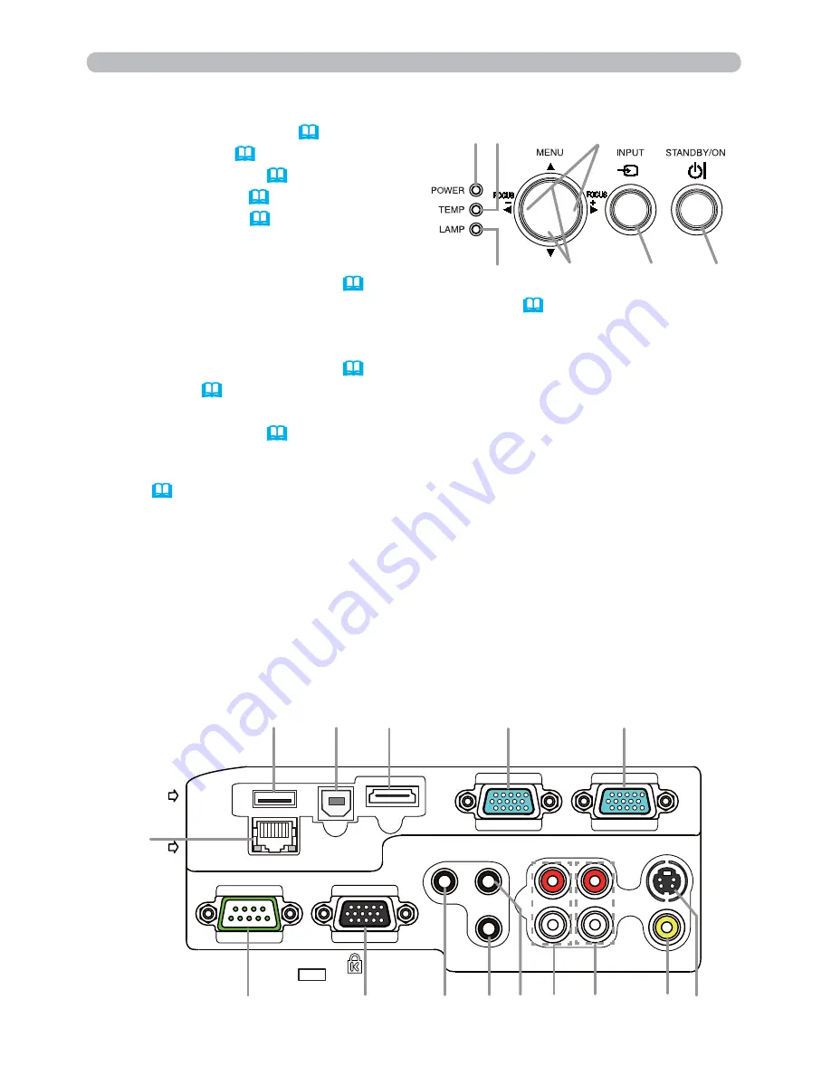
Control panel

(1) 

STANDBY/ON

 button (

18

)

(2) 

INPUT

 button (

20

)

(3) 

POWER

 indicator (

18, 101, 102

)

(4) 

TEMP

 indicator (

101, 102

)

(5) 

LAMP

 indicator (

101, 102

)

Buttons


◄/►/▲/▼

(6)  

FOCUS +

/

-

 buttons


when no menu is displayed (

24

), 


or Cursor ◄/► buttons when a menu is displayed (

28

). FOCUS +/- function 

is invalid when the 

USB TYPE A

 port is selected as the input source.

(7)  

MENU

 buttons


when no menu is displayed (

28

), or Cursor ▲/▼ buttons when a menu is 

displayed (

28

).

The ◄/►/▲/▼ buttons on the projector work only as the cursor buttons while the 
template is displayed (

52

).

Ports 

(

9 ~ 13

)

(1) 

USB TYPE A 

port


(2) 

LAN  

port 

(3)

 HDMI

 port


(4)

 USB TYPE B 

port


(5)

 MIC

 port 

(6) 

AUDIO IN1

 port 

(7) 

AUDIO IN2

 port 

(8) 

AUDIO IN3(L,R)

  ports 

(9)  

AUDIO OUT (L,R)

 ports

(10) 

COMPUTER IN1

 port 

(11) 

COMPUTER IN2

 port 

(12) 

MONITOR OUT

 port 

(13) 

CONTROL

 port

(14) 

VIDEO

 port

(15) 

S-VIDEO

 port 

COMPUTER IN1

COMPUTER IN2

HDMI

USB TYPE B

S-VIDEO

VIDEO

AUDIO OUT

AUDIO IN3

AUDIO IN1

AUDIO IN2

MIC

MONITOR OUT

CONTROL

     USB
TYPE A
   DC5V 
     0.5A

L

R

R

L

     LAN

(7)

(3)

(11)

(6)

(12)

(10)

(8)

(14)

(4)

(1)

(13)

(15)

(2)

(5)

(9)

(1)

(7)

(2)

(3)

(5)

(4)

(6)

Summary of Contents for CP-A221N

Page 1: ...t if ignored could possibly result in personal injury or even death due to incorrect handling This symbol indicates information that if ignored could possibly result in personal injury or physical damage due to incorrect handling Please refer to the pages written following this symbol Mac is a registered trademark of Apple Inc Windows DirectDraw and Direct3D are registered trademarks of Microsoft ...

Page 2: ...d from the power outlet Thank you for purchasing this projector NOTE The information in this manual is subject to change without notice The manufacturer assumes no responsibility for any errors that may appear in this manual The reproduction transmission or use of this document or contents is not permitted without express written authority WARNING Before using read these user s manuals of this pro...

Page 3: ... place flower vases pots cups cosmetics liquids such as water etc on or around the projector Do not place metals combustibles etc on or around the projector To avoid penetration of foreign objects do not put the projector into a case or bag together with any thing except the accessories of the projector signal cables and connectors Never disassemble and modify The projector contains high voltage c...

Page 4: ...n in households where children are present Use only the correct power cord and the correct power outlet Incorrect power supply could result in fire or electrical shock Use only the correct power outlet depending on the indication on the projector and the safety standard The enclosed power cord must be used depending on the power outlet to be used Be cautious of the power cord connection Incorrect ...

Page 5: ...sconnecting the power cord or cables do it with your hand holding the plug or connector Do not place the cord near the heater Avoid bending the power cord sharply Do not attempt to work on the power cord Be careful in handling the battery of the remote control Incorrect handling of the battery could result in fire or personal injury The battery may explode if not handled properly Keep the battery ...

Page 6: ... periodically If the air filter becomes clogged by dust or the like internal temperature rises and could cause malfunction The projector may display the message such as CHECK THE AIR FLOW or turn off the projector to prevent the internal heat level rising When the indicators or a message prompts you to clean the air filter clean the air filter as soon as possible If the soiling will not come off t...

Page 7: ... detergent directly Do not use an aerosol sprays solvents volatile substances or abrasive cleaner Before using chemical wipes be sure to read and observe the instructions Do not allow long term close contact with rubber or vinyl About bright spots or dark spots Although bright spots or dark spots may appear on the screen this is a unique characteristic of liquid crystal displays and such do not co...

Page 8: ...emote control sensors could invalidate the remote control Avoid radio interference Any interfering radiation could cause disordered image or noises Avoid radio generator such as a mobile telephone transceiver etc around the projector About displaying characteristic The display condition of the projector such as color contrast etc depends on characteristic of the screen because the projector uses a...

Page 9: ...is product contains a mercury lamp do not put in trash Dispose of in accord with environmental laws For lamp recycling go to www lamprecycle org in USA For product disposal contact your local government agency or www eiae org in the US or www epsc ca in Canada For more information call your dealer Do not open the lamp cover while the projector is suspended from above This is dangerous since if the...

Page 10: ...asures Reorient or relocate the receiving antenna Increase the separation between the equipment and receiver Connect the equipment into an outlet on a circuit different from that to which the receiver is connected Consult the dealer or an experienced radio TV technician for help INSTRUCTIONS TO USERS This equipment complies with the requirements of FCC Federal Communication Commission equipment pr...

Page 11: ...N H PHASE H SIZE AUTO ADJUST EXECUTE INPUT menu 38 PROGRESSIVE VIDEO NR COLOR SPACE VIDEO FORMAT HDMI FORMAT HDMI RANGE COMPUTER IN FRAME LOCK RESOLUTION SETUP menu 42 D ZOOM D SHIFT PICTURE POSITION CP A221N A301N PICT POSIT H CP AW251N KEYSTONE KEYSTONE PERFECT FIT AUTO ECO MODE ECO MODE MIRROR STANDBY MODE MONITOR OUT AUDIO menu 46 VOLUME SPEAKER AUDIO SOURCE HDMI AUDIO MIC LEVEL MIC VOLUME SCR...

Page 12: ... pictures on a screen This projector can be controlled and monitored via LAN connection This projector s network supports the PJLinkTM standard PJLinkTM is a unified standard for operating and controlling data projectors PJLinkTM enables central control of projectors manufactured by different vendors and projectors can be operated by a controller PJLinkTM compliant equipment can be managed and cont...

Page 13: ...r just after use since it is too hot Be careful not to pinch your finger with the lens door to prevent an injury Never look into the projection lens or mirror while the projection lamp lights since the projection lamp ray may cause a trouble on your eyes Do not use the security bar and slot to prevent the projector from falling down since it is not designed for it WARNING Maintain normal ventilatio...

Page 14: ... when a menu is displayed 28 The buttons on the projector work only as the cursor buttons while the template is displayed 52 Ports 9 13 1 USB TYPE A port 2 LAN port 3 HDMI port 4 USB TYPE B port 5 MIC port 6 AUDIO IN1 port 7 AUDIO IN2 port 8 AUDIO IN3 L R ports 9 AUDIO OUT L R ports 10 COMPUTER IN1 port 11 COMPUTER IN2 port 12 MONITOR OUT port 13 CONTROL port 14 VIDEO port 15 S VIDEO port COMPUTER...

Page 15: ...7 MY BUTTON 1 button 57 18 MY BUTTON 2 button 57 19 KEYSTONE button 25 20 FOCUS button 24 21 FOCUS button 24 22 D ZOOM button 23 23 D ZOOM button 23 24 POSITION button 25 29 25 MENU button 28 29 26 cursor buttons 28 27 ENTER button 28 29 28 ESC button 28 29 RESET button 28 30 Battery cover 16 Back of the remote control 30 VIDEO DOC CAMERA KEYSTONE ASPECT SEARCH BLANK MUTE MY BUTTON POSITION ESC ME...

Page 16: ...as necessary Since the projector features an ultra short throw be aware that it is required to select a screen carefully to have better performance A soft screen such as a pull down screen may cause serious distortion of a projected image A hard screen such as a board screen is recommended for use with this projector A high gain screen such as a bead screen that has narrow viewing angle is not sui...

Page 17: ...e projector Do not place the projector in a bathroom or the outdoors Do not place anything containing liquid near the projector Do not place the projector where any oils such as cooking or machine oil are used Use only the mounting accessories the manufacturer specified and leave installing and removing the projector with the mounting accessories to the service personnel Read and keep the user s ma...

Page 18: ...ay be required by EMI regulations Neither disassemble nor modify the projector and the accessories Do not use the damaged accessory Be careful not to damage the accessories Route a cable so that it is neither stepped on nor pinched out WARNING Do not turn on or off the projector while connected to a device in operation unless that is directed in the manual of the device Otherwise it may cause malf...

Page 19: ...ojector is VESA DDC 2B compatible Plug and Play can be used by connecting this projector to a computer that is VESA DDC display data channel compatible Take advantage of this feature by connecting a computer cable to the COMPUTER IN1 port DDC 2B compatible Plug and Play may not work properly if any other type of connection is attempted Please use the standard drivers in your computer as this proje...

Page 20: ...formance will be achieved if the resolutions of the input signal and the projector panel are identical If you connect this projector and a notebook computer you need output the display to an external monitor or output simultaneously to the internal display and an external monitor Consult the computer s manual for the setting Depending on the input signal the automatic adjustment function of this p...

Page 21: ...andby mode the volume of the microphone is adjustable with the VOLUME buttons on the remote control in synchronization with the volume of the projector 20 Even when the sound of projector is set to mute mode by the AUDIO SOURCE function 46 the volume of the microphone is adjustable In both modes standby or normal the MUTE button on the remote control works on the sounds of the microphone and the p...

Page 22: ...the User s Manual Network Guide for details of the network functions Before connecting the projector to a network system be sure to obtain the consent of the administrator of the network 65 Do not connect the LAN port to any network that might have the excessive voltage CAUTION If an oversized USB storage device blocks the LAN port use a USB extension cable to connect the USB storage device NOTE C...

Page 23: ...Do not distribute the power supply to multiple devices Doing so may overload the outlet and connectors loosen the connection or result in fire electric shock or other accidents WARNING Using the security bar and slot A commercial anti theft chain or wire up to 10 mm in diameter can be attached to the security bar on the projector Also this product has the security slot for the Kensington lock For d...

Page 24: ...le cover 3 Insert the three knobs on the cable cover into the three holes on the projector as shown in the figure Pass the cables through the holes on the bottom of the cable cover 1 2 3 1 2 3 1 2 3 1 2 3 knobs Setting up Be careful not to pinch the cables in the cable cover to prevent damage to the cables Use the cable cover that is supplied with the projector Do not attempt any modifications to th...

Page 25: ...surrounding environment Be sure to use only the batteries specified Do not use batteries of different types at the same time Do not mix a new battery with used one Make sure the plus and minus terminals are correctly aligned when loading a battery Keep a battery away from children and pets Do not recharge short circuit solder or disassemble a battery Do not place a battery in a fire or water Keep ba...

Page 26: ...inting device because the built in pointing device may have priority to this function Windows 95 OSR 2 1 or higher is required for this function And also this function may not work depending on the computer s configurations and mouse drivers This function can work with the computer which can operate general USB mouse or keyboard You cannot do things like press two buttons at once for instance press...

Page 27: ...NIFY PAGE DOWN ON OFF FREEZE UP 㧗 VOLUME ENTER FOCUS D ZOOM STANDBY ON button POWER indicator WARNING Never look into the projection lens or mirror while the projection lamp lights since the projection lamp ray may cause a trouble on your eyes Be careful not to pinch your finger with the lens door to prevent an injury Do not place the projector vertically with the lens door open as shown in the figu...

Page 28: ...ng in orange The lens door will close right after the lamp goes off However to maintain better picture quality the lens door will close after the lamp has been cooled down when the projector is installed upside down such as in ceiling mount installation Then POWER indicator will stop blinking and light in steady orange when the lamp cooling is complete 101 Do not turn the projector on for about 10...

Page 29: ...d To restore the sound press the MUTE VOLUME or VOLUME button Even if you do not do anything the dialog will automatically disappear after a few seconds Temporarily muting the sound When is selected for current picture input port the sound is always muted Please see AUDIO SOURCE item of AUDIO menu 46 C C Closed Caption is automatically activated when sound is muted and an input signal containing C...

Page 30: ... selected for AUTO SEARCH item in OPTION menu the projector will keep checking every port sequentially till an input signal is detected 54 If COMPUTER button is pressed when VIDEO S VIDEO or HDMI port is selected the projector will check COMPUTER IN1 port first It may take several seconds to project the images from the USB TYPE B port 1 Press the MY SOURCE DOC CAMERA button on the remote control Th...

Page 31: ...he operation Searching an input signal While ON is selected for AUTO SEARCH item in OPTION menu 54 the projector will keep checking the ports in above order repeatedly till an input signal is detected It may take several seconds to project the images from the USB TYPE B port For a computer signal NORMAL 4 3 16 9 16 10 NATIVE For a video signal s video signal or component video signal 4 3 16 9 16 1...

Page 32: ...on do not touch these buttons for a few seconds until the dialog is disappeared If you want to expand a part of the image use the magnify function 26 Keep the spacers away from children and pets Be careful not to let them swallow the spacers If swallowed consult a physician immediately for emergency treatment WARNING The adjustment angle can be adjusted up to plus or minus 1 each of FRONT and REAR...

Page 33: ...or a video signal a certain extra such as a line may appear outside a picture When this function is performed for a computer signal a black frame may be displayed on the edge of the screen depending on the PC model The items adjusted by this function may vary when the FINE or DISABLE is selected for the AUTO ADJUST item of the SERVICE item in the OPTION menu 59 For a component video signal The ver...

Page 34: ... will appear on the screen to aid you in correcting the distortion Correcting the keystone distortions 2 Use the cursor buttons to select MANUAL or PERFECT FIT operation and press the button to perform the following 1 MANUAL displays a dialog for keystone correction Use the buttons to select KEYSTONE KEYSTONE then use the buttons for adjustment 2 PERFECT FIT displays a dialog for adjusting the sha...

Page 35: ... component video signals or HDMITM Component signals 1 5 times 2 times 1 time While the triangles are displayed on the dialog use the cursor buttons to shift the magnifying area Press the MAGNIFY OFF button on the remote control to exit magnification The MAGNIFY dialog will automatically disappear in several seconds with no operation The dialog will appear again if the MAGNIFY ON button is pressed ...

Page 36: ...ill go into the FREEZE mode which the picture is frozen To exit the FREEZE mode and restore the screen to normal press the FREEZE button again Temporarily freezing the screen The projector automatically exits from the FREEZE mode when some control buttons are pressed If the projector continues projecting a still image for a long time the LCD panel might possibly be burned in Do not leave the proje...

Page 37: ...splaying any menu the MENU button on the projector works as the cursor buttons The basic operations of these menus are as follows In the EASY MENU continued on next page 1 Use the cursor buttons to select a menu If you want to change it to the EASY MENU select the EASY MENU The items in the menu appear on the right side 2 Press the cursor button or ENTER button to move the cursor to the right side...

Page 38: ...T button on the remote control during the operation Note that some items ex LANGUAGE VOLUME cannot be reset In the ADVANCED MENU when you want to return to the previous display press the cursor button or ESC button on the remote control Indication in OSD On Screen Display The meanings of the general words on the OSD are as follows Indication Meaning EXIT Selecting this word finishes the OSD menu It...

Page 39: ...enu might be displayed outside of the image display area depending on the adjustment value of the ASPECT D ZOOM KEYSTON and KEYSTONE Changing the values of ASPECT D ZOOM KEYSTONE and KEYSTONE may fix the symptom KEYSTONE Using the buttons corrects the vertical keystone distortion See the KEYSTONE item in SETUP menu 43 KEYSTONE Using the buttons corrects the horizontal keystone distortion See the KE...

Page 40: ...operated but it is not a malfunction ECO MODE Using the buttons changes the eco mode setting See the ECO MODE item in SETUP menu 45 MIRROR Using the buttons switches the mode for mirror status See the MIRROR item in SETUP menu 45 RESET Performing this item resets all of the EASY MENU items except the FILTER TIME and LANGUAGE A dialog is displayed for confirmation Selecting the OK using the button p...

Page 41: ... an item using the buttons and adjust the level using the buttons You can display a test pattern for checking the effect of your adjustment by pressing the ENTER button Each time you press the ENTER button the pattern changes as below No pattern Gray scale of 9 steps Ramp Gray scale of 15 steps The eight equalizing bars correspond to eight tone levels of the test pattern Gray scale of 9 steps exce...

Page 42: ... Lines or other noise might appear on the screen when this function is operated but it is not a malfunction COLOR Using the buttons adjusts the strength of whole color Weak Strong This item can be selected only for a video s video and component video signal For an HDMITM signal this item can also be selected if either 1 or 2 applies 1 HDMI FORMAT item in the INPUT menu is set to VIDEO 2 HDMI FORMA...

Page 43: ...he or ENTER button performs each function SAVE 1 SAVE 2 SAVE 3 SAVE 4 LOAD 4 LOAD 3 LOAD 2 LOAD 1 SAVE 1 SAVE 2 SAVE 3 SAVE 4 Performing a SAVE function saves the current adjustment data into the memory linked in the number included in the function s name Remember that the current data being stored of a memory will be lost by saving new data into the memory LOAD 1 LOAD 2 LOAD 3 LOAD 4 Performing a...

Page 44: ... signal 4 3 16 9 16 10 14 9 NATIVE For an input signal from the LAN USB TYPE A or USB TYPE B port or if there is no signal CP A221N CP A301N 4 3 fixed CP AW251N 16 10 fixed The NORMAL mode keeps the original aspect ratio of the signal OVER SCAN Using the buttons adjusts the over scan ratio Small It magnifies picture Large It reduces picture This item can be selected only for a video s video and compo...

Page 45: ... set to 10 This function is unavailable for a signal from the LAN USB TYPE A USB TYPE B or HDMI port H POSITION Using the buttons adjusts the horizontal position Right Left Over adjusting the horizontal position may cause noise to appear on the screen If this occurs please reset the horizontal position to the default setting Pressing the RESET button when the H POSITION is selected will reset the ...

Page 46: ...hat the application window is set to its maximum size prior to attempting to use this feature A dark picture may still be incorrectly adjusted Use a bright picture when adjusting For a video signal and s video signal The video format best suited for the respective input signal will be selected automatically This function is available only when the AUTO is selected for the VIDEO FORMAT item in the ...

Page 47: ...in defect for example jagged line of the picture for a quick moving object In such a case please select OFF even though the screen image may lose sharpness VIDEO NR Using the buttons switches the noise reduction mode HIGH MID LOW This function works only for a video signal s video signal compo nent video signal of 480i 60 or 576i 50 or 1080i 50 60 and an HDMITM signal of 480i 60 or 576i 50 or 1080...

Page 48: ... the input signal HDMI FORMAT Using the cursor buttons switches the video format for an input from the HDMI port AUTO VIDEO COMPUTER Feature AUTO automatically sets the optimum mode VIDEO sets the suitable mode for DVD signals COMPUTER sets the suitable mode for computer signals When the COMPUTER is selected the functions COLOR PICTURE menu TINT PICTURE menu and OVER SCAN IMAGE menu are unavailabl...

Page 49: ...of component video input to COMPUTER IN1 2 port In the AUTO mode the picture may be distorted with certain input signals In such a case remove the signal connector so that no signal is received and select the SYNC ON G OFF and then reconnect the signal FRAME LOCK Set the frame lock function on off for each port 1 Use the buttons to select the input ports 2 Use the buttons to turn the frame lock fu...

Page 50: ...To set a custom resolution use the buttons to select the CUSTOM and the RESOLUTION_CUSTOM box will be displayed Set the horizontal HORZ and vertical VERT resolutions using the buttons This function may not support all resolutions 5 Move the cursor to OK on screen and press the or ENTER button The message ARE YOU SURE YOU WISH TO CHANGE RESOLUTION appears To save the setting press the button The ho...

Page 51: ... position The D SHIFT adjustment values are not valid when the D ZOOM is set to 256 full screen CP A221N CP A301N The D SHIFT adjustment values are not valid when the D ZOOM is set to 320 full screen CP AW251N PICTURE POSITION CP A221N CP A301N Using the cursor buttons selects the vertical picture position TOP MID BOTTOM The PICTURE POSITION is not changed if any of the following cases apply The A...

Page 52: ...ALID SCAN FREQ The BLANK or TEMPLATE function is selected KEYSTONE Using the buttons corrects the vertical keystone distortion Shrink the bottom of the image Shrink the top of the image The adjustable range of this function will vary among inputs For some input this function may not work well This function will be unavailable when the Transition Detector is on 75 or the PERFECT FIT 44 is adjusted ...

Page 53: ...PERFECT FIT function keystone adjustment feature is unavailable To correct the keystone distortion reset the adjustment of all the corners and sides The adjustable range of this correction will vary among inputs For some input this function may not work well One adjustment position common to the top and bottom sides can be set Also another adjustment position common to the left and right sides can...

Page 54: ...tion control except to turn the projector on and the network function are disabled while the projector is in the standby mode If the COMMUNICATION TYPE in the COMMUNICATION menu is set to NETWORK BRIDGE all of the RS 232C commands are disabled 62 When SAVING is selected STANDBY setting of AUDIO SOURCE 46 is invalid and no signal is output from AUDIO OUT port in the standby mode When SAVING is sele...

Page 55: ...r does not work when SPEAKER is set to OFF 1 Choose a picture input port using the buttons Choose STANDBY to select the sound output in the standby mode 2 Select one of the AUDIO IN ports using buttons Select to mute the sound from the input port or in the standby mode chosen in the step 1 In the AUDIO SOURCE window H symbolizes the audio signal from the HDMI port It can be selected only for the p...

Page 56: ...he suitable one for your HDMITM audio device 1 2 MIC LEVEL Using the buttons switches the input level to match that of the microphone connected to the MIC port HIGH LOW HIGH for a microphone with an amplifier LOW for a microphone without an amplifier MIC VOLUME Using the buttons adjusts the volume of the microphone connected to the MIC port Low High ...

Page 57: ...on on the remote control MyScreen ORIGINAL BLUE WHITE BLACK MyScreen Screen can be registered by the MyScreen item 49 ORIGINAL Screen preset as the standard screen BLUE WHITE BLACK Plain screens in each color To avoid remaining as an afterimage the MyScreen or ORIGINAL screen will change to the plain black screen after several minutes START UP Using the buttons switches the mode for the start up s...

Page 58: ...the position of the image which you want to use The frame may not be able to be moved for some input signals To start registration press the ENTER or INPUT button on the remote control To restore the screen and return to the previous dialog press the RESET button on the remote control Registration may take several minutes When the registration is completed the registered screen and the following m...

Page 59: ...g while searching for the input Detecting while an input signal is detected AUTO ECO MODE while starting up with AUTO ECO MODE The indication of the input signal displayed by changing The indication of the aspect ratio displayed by changing The indication of the PICTURE MODE displayed by changing The indication of the ACTIVE IRIS displayed by changing The indication of the MY MEMORY displayed by c...

Page 60: ... blank until a name is specified 3 Select an icon you would like to assign to the port in the SOURCE NAME dialog The name assigned to the port will also be automatically switched according to your icon selection Press the ENTER or INPUT button to determine your icon selection 4 Select a number you would like to assign to the port along with the icon You can select the number either from blank no nu...

Page 61: ...he same procedure as described at the item 6 above 8 To finish entering text move the cursor to the OK on screen and press the ENTER or INPUT button To revert to the previous name without saving changes move the cursor to the CANCEL on screen and press the ENTER or INPUT button TEMPLATE Using the cursor buttons switches the mode for the template screen Press the cursor or the ENTER button to displa...

Page 62: ...f The caption is not displayed when the OSD menu is active The Closed Caption is the function to display the dialogue narration and or sound effects of a television program or other video sources The Closed Caption availability is depending upon broadcaster and or content MODE Select Closed Caption MODE setting from following options using buttons CAPTIONS TEXT CAPTIONS Display Closed Caption TEXT...

Page 63: ...stop searching and display the image COMPUTER IN1 COMPUTER IN2 LAN USB TYPE A VIDEO S VIDEO HDMI USB TYPE B It may take several seconds to project the images from the USB TYPE B port DIRECT POWER ON Using the buttons turns on off the DIRECT POWER ON function ON OFF When set to the ON the lamp in projector will be automatically turned on without the usual procedure 18 only when the projector is sup...

Page 64: ...t To use this function you need to connect the USB TYPE B port of the projector and the type A USB port of a computer MOUSE USB DISPLAY MOUSE The accessory remote control works as the simple mouse and keyboard of the computer USB DISPLAY The port works as an input port that receives image signals from the computer 87 It may take several seconds to project the images from the USB TYPE B port In the...

Page 65: ... about the lamp For the lamp replacement see the section Replacing the lamp 92 FILTER TIME The filter time is the usage time of the air filter counted after the last resetting It is shown in the OPTION menu Pressing the RESET button on the remote control or the button of the projector displays a dialog To reset the filter time select the OK using the button CANCEL OK Please reset the filter time only ...

Page 66: ...DEO Selects the input from VIDEO port SLIDESHOW Selects the input from USB TYPE A port and starts a Slideshow MY IMAGE Displays the MY IMAGE menu 68 MESSENGER Turns the messenger text displayed on the screen on off Messenger Function in the User s Manual Network Guide When there is no transferred text data to display the message NO MESSENGER DATA appears INFORMATION Displays SYSTEM_INFORMATION INP...

Page 67: ... to adjust the magnification ratio D SHIFT Turns the D SHIFT mode on off When the D SHIFT mode is on use the cursor buttons to move the magnifying area RESOLUTION Turns on off the RESOLUTION dialog 41 MIC VOLUME Turns on off the MIC VOLUME dialog 47 ECO MODE Turns on off the ECO MODE dialog 45 MY SOURCE Using buttons selects the picture input port to be selected with pressing the MY SOURCE DOC CAME...

Page 68: ...k correctly In such a case please choose DISABLE to disable the automatic adjustment and make adjustment manually GHOST 1 Select a color element of ghost using the buttons 2 Adjust the selected element using the buttons to disappear ghost FILTER MESSAGE Use the button to set the timer for notifying by the message when to replace the filter unit 500h 1000h 2000h 3000h 4000h 5000h OFF After choosing ...

Page 69: ...low impact to the lens door as it incorporates a mirror Keep the projector out of the reach of children Never touch a lens door or mirror If the mirror is broken the projected image will be distorted Close the lens door and contact your dealer When the LENS DOOR LOCK is set to ON and the lens door is not open completely for some reason the image may shift or have keystone distortion In that case u...

Page 70: ...MMUNICATION Selecting this item displays COMMUNICATION menu In this menu you can configure the serial communication settings of the projector using the CONTROL port Select an item using the cursor buttons Then pressing the button opens the submenu for the setting item you selected Or pressing the button instead of the button makes the menu back to the previous one without changing the setup Each su...

Page 71: ...elow SERIAL SETTINGS Select the serial communication condition for the CONTROL port BAUD RATE 4800bps 9600bps 19200bps 38400bps PARITY NONE ODD EVEN The BAUD RATE is fixed to 19200bps and PARITY is fixed NONE when the COMMUNICATION TYPE is set to OFF above TRANSMISSION METHOD Select the transmission method for communication by the NETWORK BRIDGE from the CONTROL port HALF DUPLEX FULL DUPLEX HALF DUP...

Page 72: ...vice that the projector sends data to In this mode the projector can send out data from the computer continuously 1s 2s 3s Select the time period to keep the projector waiting for response from the device that the projector sends data to While waiting the response the projector does not send out any data from the CONTROL port This menu is available only when the NETWORK BRIDGE is selected for the ...

Page 73: ...em can t be selected for no signal and sync out When the MY TEXT DISPLAY is set to ON the MY TEXT is displayed together with the input information in the INPUT_ INFORMATION box 77 FACTORY RESET Selecting OK using the button performs this function By this function all the items in all of menus will collectively return to the initial setting Note that the items LAMP TIME FILTER TIME LANGUAGE FILTER ...

Page 74: ...rk Guide then you must set the DATE AND TIME during the initial installation The network communication control is disabled while the projector is in standby mode if the STANDBY MODE item of SETUP menu is set to SAVING Please connect the network communication to the projector after setting the STANDBY MODE to NORMAL 45 NOTE Item Description SETUP Selecting this item displays the SETUP Menu for the ...

Page 75: ...omputer network that serves as an access point to another network address This function can only be used when DHCP is set to OFF DNS SERVER Use the buttons to input the DNS server address The DNS server is a system to control domain names and IP addresses on the Network TIME DIFFERENCE Use the buttons to enter the TIME DIFFERENCE Set the same TIME DIFFERENCE as the one set on your computer If unsu...

Page 76: ...or ALL CLEAR on screen and push the ENTER or INPUT button 1 character or all characters will be erased The PROJECTOR NAME can be input up to 64 characters 3 To change an already inserted character press the button to move the cursor to one of the first 3 lines and use the buttons to move the cursor on the character to be changed After pressing the ENTER or INPUT button the character is selected The...

Page 77: ... characters or less To switch the image displayed Use the buttons To return to the menu Press the button on the remote control To erase the image displayed and its source file in the projector 1 Press the RESET button on the remote control while displaying an image to display the MY IMAGE DELETE menu 2 Press the button to perform to erase To stop erasing press the button AMX D D AMX Device Discover...

Page 78: ...ose OK in the dialog The Presenter mode is cancelled and a message is displayed indicating the result To make Presenter mode setting use LiveViewer For details see the section Presenter mode in the User s Manual Network Guide MULTI PC MODE If you set one or more computers to the Multi PC mode on LiveViewer and send their images to the projector you can select the display mode on the projector from...

Page 79: ...de to Multi PC mode on your computer see the section Switching the display mode in the User s Manual Network Guide The Presenter mode setting of the selected computer becomes valid when the display mode is changed to Single PC mode Also the Presenter mode setting becomes invalid when the display mode is changed to Multi PC mode regardless the setting on the computers For details see the section Pr...

Page 80: ...decreases the set time may become incorrect even though accurate date and time are input Replace the battery suitably 96 IP ADDRESS SUBNET MASK and DEFAULT GATEWAY indicate 0 0 0 0 when DHCP is ON and the projector has not gotten address from DHCP server SERVICE Executing this item restarts and initializes the network functions Choose the RESTART EXECUTE using the button Then use the button to exe...

Page 81: ... PASSWORD box will be displayed 2 Use the buttons to enter the registered password The factory default password is as follows CP A221N CP A301N 6215 CP AW251N 4615 This password can be changed below Move the cursor to the right side of the ENTER PASSWORD box and press the button to display the SECURITY menu It is strongly recommended the factory default password to be changed as soon as possible I...

Page 82: ...urn to MyScreen PASSWORD on off menu When a password is set for MyScreen The MyScreen registration function and menu will be unavailable The MyScreen Lock menu will be unavailable The START UP setting will be locked on MyScreen and the menu will be unavailable Turning the MyScreen PASSWORD off will allow normal operation of these functions Please do not forget your MyScreen PASSWORD 2 Turning off ...

Page 83: ...ain If an incorrect PIN code is input 3 times the projector will turn off Afterwards the projector will turn off every time an incorrect PIN code is input The projector will also turn off if there is no key input for about 5 minutes while the Enter PIN code box is displayed This function will activate only when the projector is started after AC power is turned off Please do not forget your PIN cod...

Page 84: ... the right side of the NEW PASSWORD AGAIN box and press the button to display the NOTE NEW PASSWORD box for about 30 seconds please make note of the password during this time Pressing the ENTER button on the remote control or the button on the projector will return to the TRANSITION DETECTOR on off menu Please do not forget your TRANSITION DETECTOR password This function will activate only when th...

Page 85: ...ight side of the NEW PASSWORD AGAIN box and press button to display the NOTE NEW PASSWORD box for about 30 seconds then please make note of the password during this time Pressing the ENTER button on the remote control or button on the projector will return to the MY TEXT PASSWORD on off menu 2 Turning off the MY TEXT PASSWORD 2 1 Follow the procedure in 1 1 to display the MY TEXT PASSWORD on off m...

Page 86: ...NTER or INPUT button to select and enter characters To erase 1 character at one time press the RESET button or press the and INPUT button at the same time Also if you move the cursor to DELETE or ALL CLEAR on screen and press the ENTER or INPUT button 1 character or all characters will be erased The MY TEXT can be input up to 24 characters on each line 3 To change an already inserted character pre...

Page 87: ...evices with security software may not work Be careful when inserting or removing a USB device 12 81 Files with a resolution greater than XGA are not supported Files with a resolution smaller than 36x36 are not supported Files with a resolution smaller than 100x100 may not be displayed Some supported files may not be displayed Only a frame appears when the content of image data cannot be displayed i...

Page 88: ...ges are displayed in a screen If you wish you can jump into the Full Screen mode or Slideshow mode after you select some images in the Thumbnail mode The Thumbnail mode will be started as the primary function of the PC LESS Presentation after selecting the USB TYPE A port as the input source Presentation tools Thumbnail menu Selected image Thumbnail images ...

Page 89: ...his setting information will be saved in the playlist txt file 86 ROTATE Press the cursor button or ENTER to rotate the selected image 90 degrees clockwise This setting information will be saved in the playlist txt file 86 You can control the images in the Thumbnail screen with the remote control or keypad or a web browser software The following functions can be supported while the Thumbnail is disp...

Page 90: ... order by file date Go to previous next page SLIDESHOW Configures and starts the Slideshow 84 RETURN Press the cursor button or ENTER to return to the Thumbnail screen PLAY Press the cursor button or ENTER to start the Slideshow START Sets the beginning number of the Slideshow STOP Sets the end number of the Slideshow INTERVAL Sets the interval time of the Slideshow PLAY MODE Selects the Slideshow m...

Page 91: ...tures in 1 page as maximum It is not possible to change the input port by using the INPUT button when the Thumbnail screen Slideshow or Full Screen is displayed Some error icons will be displayed in the Thumbnail NOTE This file seems to be broken or not supported format A file that cannot be displayed on the thumbnail screen is indicated by a file format icon ...

Page 92: ...n Functions The remote control The keypad on the projector Web Remote in web browser software or PAGE DOWN or or PAGE DOWN Shows the next picture or PAGE UP or or PAGE UP Shows the previous picture ENTER INPUT ENTER Displays Thumbnail These operations are not accessible while the projector OSD is displayed It is not possible to change the input port by using the INPUT button when the Thumbnail scr...

Page 93: ...will be held on screen till the ENTER button on the remote control or Web Remote Control or INPUT button on the projector is pushed NOTE You can start this function from the Slideshow menu To display the Slideshow menu select the SLIDESHOW button in the Thumbnail mode and press the ENTER button on the remote control or INPUT button on the projector Button operation Functions The remote control The...

Page 94: ...take more than several seconds to read and display an image file if it is stored in very deep layer directory or if so many files are stored in the same directory 6 PLAY MODE Select the Slideshow mode ONE TIME Play the Slideshow one time ENDLESS Play the Slideshow endless The settings of the Slideshow are saved to the playlist txt file that is stored in the storage media If the file is not existed it ...

Page 95: ...P INTERVAL and PLAY MODE settings 85 2nd line and after file name interval time rotation setting and skip setting interval time It can be set from 0 to 999900 ms with an increment of 100 ms rotation setting rot1 means a rotation at 90 degrees clockwise rot2 and rot3 increase another 90 degrees in order skip setting SKIP means that the image will not be displayed in the Slideshow The maximum length ...

Page 96: ...while the screen saver is running The image transmission from the computer is suspended while the password protected screen saver is running To resume the transmission exit the screen saver If Waiting for connection remains displayed while the USB cable is connected remove the USB cable and reconnect after a while Please check and get the latest version at Hitachi Web site http www hitachi america...

Page 97: ...iewer Lite for USB If any application software having the firewall function is installed into your computer make the firwall function invalid with following the user s manual Some security software may block image transmission Please change the security software setting to allow the use of LiveViewer Lite for USB If the computer in use is equipped with HDMI port the audio setting will be changed and...

Page 98: ...mages will be displayed w Stop button The image transmission is stopped e Hold button The image on the projector s screen is temporally frozen The last image before the button is clicked is remained on the screen You can revise the image data on your computer without showing it on the projector s screen r Option button The Options window is displayed t Minimize button The Floating menu is closed a...

Page 99: ...ality takes priority over Speed It makes JPEG compression rate lower The screen on the projector is rewritten slower because the transferred data is larger but the image quality is better Keep PC resolution If you remove the check mark from the Keep PC resolution box the screen resolution of your computer will be switched as follows and the display speed may be faster CP A221N CP A301N 1024 x 768 ...

Page 100: ...he LiveViewer Lite for USB Display LiveViewer Lite for USB If you want to display LiveViewer application window to the screen please check the box The annotation layer may not display on the projector image when this option is OFF NOTE USB Display continued ...

Page 101: ...ver loosen any other screws 5 Insert the new lamp and retighten firmly the 2 screws of the lamp that are loosened in the previous process to lock it in place 6 While putting the interlocking parts of the lamp cover and the projector together slide the lamp cover back in place Then firmly fasten the screw of the lamp cover 7 Turn the projector on and reset the lamp time using the LAMP TIME item in th...

Page 102: ...rticles that come out from the projector s vent holes and not to get them into your eyes or mouth Before replacing the lamp turn the projector off and unplug the power cord then wait at least 45 minutes for the lamp to cool sufficiently Handling the lamp while hot can cause burns as well as damaging the lamp Never unscrew except the appointed marked by an arrow screws Do not open the lamp cover wh...

Page 103: ...filter cover 3 Slide the filter unit upward to take it off from the projector 4 Use a vacuum cleaner for the filter vent of the projector 5 Take the fine meshed filter out while holding the filter cover It is recommended to leave the coarse meshed filter in the filter cover as it is 7 Put the fine meshed filter on the coarse meshed one turning its stitched side up 8 Put the filter unit back into the projecto...

Page 104: ...lter becomes clogged by dust or the like internal temperatures rise and could cause a fire a burn or malfunction to the projector WARNING Please replace the air filter when it is damaged or heavily soiled When you replace the projection lamp please replace the air filter An air filter of specified type will come together with a replacement lamp for this projector Please reset the filter time only when y...

Page 105: ...lock battery This projector has internal clock that uses a battery When the clock of the network function does not work correctly please try solution by replacement of the battery HITACHI MAXELL or HITACHI MAXELL ENERGY part number CR2032 or CR2032H NOTE The internal clock will be initialized by removing the battery For setting the clock see the User s Manual Network Guide 1 Turn the projector off...

Page 106: ...rd with the lens door opened 2 The power indicator will light in orange and the lens door closes automatically Do not touch the lens door when the door is closing Do not allow anything to obstruct the lens door When the lens door is closed manually it may not shut properly 㩷The lens door may not close when the LENS DOOR LOCK function of the SERVICE item in the OPTION menu is set to ON Refer to the...

Page 107: ...sols or sprays WARNING Please take right care of the projector according to the following Incorrect care could cause not only an injury but adverse influence such as discoloration peeling paint etc Do not use cleaners or chemicals other than those specified in this manual Do not polish or wipe with hard objects NOTICE Do not directly touch the lens surface with hands CAUTION Inside of the projector ...

Page 108: ...nd several minutes it will be reappeared every time the power is turned on Message Description There is no input signal Please confirm the signal input connection and the status of the signal source The USB TYPE B port is selected as the picture input source even if MOUSE is selected for USB TYPE B 55 Select USB DISPLAY in the dialog to project the picture input to the USB TYPE B port In this case ...

Page 109: ...sed at an altitude of about 1600 m or higher If the projector is used at an altitude of about 1600 m or higher set FAN SPEED of the SERVICE item in the OPTION menu to HIGH 59 A note of precaution when cleaning the air filter Please immediately turn the power off and clean or change the air filter referring to the Cleaning and replacing the air filter section of this manual After you have cleaned or c...

Page 110: ...utes After the projector has sufficiently cooled down please make confirmation of the following items and then turn the power on again Is there blockage of the air passage aperture Is the air filter dirty Does the peripheral temperature exceed 35 C If the same indication is displayed after the remedy please change the lamp referring to the section Replacing the lamp Blinking In Red or Lighting In Red...

Page 111: ...jector is used at an altitude of about 1600 m or higher set FAN SPEED of the SERVICE item in the OPTION menu to HIGH 59 Lighting In Red Turned off Turned off The lens door is not opened properly One of the followings has been happened The lens door is not opened properly when the projector is turned on The lens door position is shifted while the projector is working Restart the projector after con...

Page 112: ...rojector has sufficiently cooled down please make confirmation of the attachment state of the lamp and lamp cover and then turn the power on again 92 Neither sounds nor pictures are outputted The signal cables are not correctly connected Correctly connect the connection cables 9 13 Signal source does not correctly work Correctly set up the signal source device by referring to the manual of the sourc...

Page 113: ...ted to an extremely low level Adjust BRIGHTNESS to a higher level using the menu function 32 The computer cannot detect the projector as a plug and play monitor Make sure that the computer can detect a plug and play monitor using another plug and play monitor 10 The BLANK screen is displayed Press BLANK button on the remote control 27 The USB TYPE B port is selected as the picture input source eve...

Page 114: ...et AUTO ECO MODE to OFF in the SETUP menu 44 45 The lamp is approaching the end of its product lifetime Replace the lamp 92 93 Pictures appear blurry Either the focus and or horizontal phase settings are not properly adjusted Adjust the focus using the FOCUS button and or H PHASE using the menu function 24 37 The lens is dirty or misty Clean the lens referring to the section Caring for the lens 97...

Page 115: ... POWER indicator blinks in orange a few times Goes into standby mode Disconnect the LAN cable and check that the projector is working properly If this phenomenon occurs after connecting to the network there may be a loop between two Ethernet switching hubs within the network as explained below There are two or more Ethernet switching hubs in a network Two of the hubs are doubly connected by LAN ca...

Page 116: ...the plural number of independent software modules and there exist our copyright or and third party copyrights for each of such software modules Be sure to read End User License Agreement for the Projector Software which is separated document in the CD Please see the Specifications in the User s Manual concise which is a book ...

Page 117: ...es transmitted through a network 38 Web Control allows you to monitor and control the projector through a network from a computer 46 My Image allows the projector to store up to four still images and project them 71 Messenger allows the projector to display text sent from a computer through a network 73 Network Bridge allows you to control an external device through the projector from a computer 7...

Page 118: ...ction method 15 1 5 1 Passcode connection 16 1 6 Manual Configuration 24 1 6 1 Profile connection 24 1 6 2 History connection 25 1 7 Configuring the network settings manually 26 1 8 Confirming the connection to your destination 31 1 8 1 Connection and transmission 31 1 8 2 Connection error 33 1 9 Profile data 34 1 9 1 Outline of Profile data 34 1 9 2 Making Profile data 34 1 9 3 Editing Profile data 35 1 ...

Page 119: ... 68 3 12 Projector Status 69 3 13 Network Restart 70 4 My Image Function 71 5 Messeger Function 73 6 Network Bridge Function 75 6 1 Connecting devices 75 6 2 Communication setup 76 6 3 Communication port 76 6 4 Transmission method 77 6 4 1 HALF DUPLEX 77 6 4 2 FULL DUPLEX 78 7 Other Functions 79 7 1 E mail Alerts 79 7 2 Projector Management using SNMP 81 7 3 Event Scheduling 82 7 4 Command Control...

Page 120: ...me Premium Professional Ultimate Enterprise 32 bit version only CPU Pentium 4 2 8 GHz or higher Graphic card 16 bit XGA or higher When using the LiveViewer it is recommended that the display resolution of your computer is set to 1024 x 768 Memory 512 MB or higher Hard disk space 100 MB or higher Web browser Internet Explorer 6 0 or higher CD ROM drive The network communication control is disabled ...

Page 121: ...d the display speed may become faster If your computer does not support the display resolution specified above a smaller resolution that is the largest among the resolutions that are supported by the computer will be selected Images might not been transmitted caused by OS version or the driver software for Network Adapter on your computers It is highly recommended that OS and the driver should be u...

Page 122: ...ou will need to replace E with the correct drive letter assigned to your CD ROM drive If the software has been already installed Uninstallation will be done Click the Cancel button then uninstallation will be canceled If you uninstalled the software by miss operation please re install the software from first procedure 5 After a moment the Welcome dialog will appear as shown on the right Press the N...

Page 123: ...Windows Vista or Windows 7 Please click the Install this driver software anyway and continue installation 10 After a moment installation will complete and the Setup Complete dialog will appear as shown on the right Click the Finish This completes the software installation Then your computer automatically restarts 1 To confirm that the software has been properly installed press the Start button on t...

Page 124: ...nual require the LiveViewer Version 4 xx In the version information a number between 00 and 99 will replace the xx LiveViewer function use depends on the model you are using If you want to use the latest downloaded LiveViewer please refer for the appropriate group item in the LiveViewer User s Manual This model will be in the group of D 1 Connection to the network 1 2 Installing the LiveViewer con...

Page 125: ...nnection quickly and easily q Selecting the network connection mode Wireless LAN Wired LAN My Connection w Selecting the network connection method Enter PassCode Configure Manually Select From List e Manual configuration Profile History Configure Network Settings Manually r Configuring the network settings manually t Confirming the connection to your destination Wireless LAN can be selected only when an...

Page 126: ...ter Select Start All Programs Projector Tools LiveViewer on Windows menu Then proceed to item 1 4 Selecting the network connection mode 11 1 3 Process to connect the network continued 1 Connection to the network After sequence the User Account Control UAC dialog will appear if you are using Windows Vista or Windows 7 Please click Allow to start LiveViewer NOTE ...

Page 127: ... select either the wireless LAN or wired LAN a list of the network adapters in your computer is shown in the menu Select what you like to use in the list and click the Next Then proceed to item 1 5 Selecting the network connection method 15 1 4 1 Selecting either the wireless LAN or wired LAN Are you sure that you want to turn on the network adapter The screen is displayed in the case that the sel...

Page 128: ...layed in the case that the projector is not connected with a LAN cable to your computer when the wired LAN is selected Be sure that the projector is connected with a LAN cable to your computer Click the OK then the screen is back to the previous one to select the network connection mode 1 Connection to the network ...

Page 129: ...ed to the projector through the network by using the profile data that is pre assigned to My Connection 36 When you select the My Connection the computer immediately starts the connection to the projector 1 4 2 Selecting My Connection A network connection could not be established Windows prevented network configuration changes You may log in the Windows under User authority Click the OK to return to...

Page 130: ...ected is already used for another network connection To connect click the Yes Proceed to item 1 8 Confirming the connection to your destination 31 Not to connect click the No to return to the screen to select the network connection mode 11 1 Connection to the network 1 4 Selecting the network connection mode continued ...

Page 131: ... select which projector you would like to send your images Proceed to 1 8 Confirming the connection to your destination 31 Enter PassCode If you want to use the Passcode for network connection select the Enter PassCode and click the Next The Passcode is given by the projector on screen And you simply input the Passcode to the LiveViewer to connect the network Proceed to item 1 5 1 Passcode connecti...

Page 132: ...s A or B or C The Passcode system accepts Class A B and C only Class A 255 0 0 0 ClassB 255 255 0 0 Class C 255 255 255 0 NOTE The Passcode is 12 digit code consisting of alphanumeric characters 1 9 and A Z Example PASSCODE 1234 5678 9ABC The Passcode is given on the projector when the LAN port is selected as input source 1 Getting the Passcode There are two methods to get the Passcode from the pr...

Page 133: ...ETWORK and use the cursor button to enter the item 5 Use the cursor buttons to select the INFORMATION and use the cursor button to display the INFORMATION 6 The Passcode appears in the INFORMATION window Method 2 Take the method 2 when you project your computer image by the LiveViewer or when the LAN port is not selected as input source If no communication between the projector and computer in 5 m...

Page 134: ...es total 12 digit Example PASSCODE 1234 5678 9ABC 2 Entering the Passcode After entering the Passcode click the Connect to start the connection to the projector Proceed to item 1 8 Confirming the connection to your destination 31 If you click the Back the screen is back to item 1 5 Selecting the network connection method 15 Troubleshooting Incorrect PassCode The incorrect Passcode was input Click t...

Page 135: ...or if the Network configuration displayed on the dialog is OK and then click the Yes A network connection could not be established If you need to add a Network configuration on your computer to connect to the projector Consult to the network administrator Log in the Windows under Administrator authority After that please resume at item 1 3 2 Starting the LiveViewer 10 Click the NO then the LiveViewe...

Page 136: ...ion If the connection is not available with the entered Network configuration a warning dialog shown to the right will be displayed Click the OK to return to the dialog for changing the Network configuration and then enter appropriate configuration If you put a check mark in the box Not displaying confirmation dialog for adding Network settings the projector memorizes current configuration and this dia...

Page 137: ...connection to your destination 31 Not to connect click the No then the LiveViewer main menu is displayed even though the network is not established Click on the main menu to go back to item 1 5 Selecting the network connection method 15 Are you sure you want to connect the selected projector 1 Connection to the network 1 5 Selecting the network connection method continued ...

Page 138: ...ing on the projector 3 Enter the following information 1 The setting on the access point 1 Enter the following information 3 Click the Connect 4 The wireless connection will be established Proceed to item 1 8 Confirming the connection to your destination 31 1 Contact the network administrator to find out the setting on the access point 2 If you use an encryption you need to set it Contact the networ...

Page 139: ...find it out 1 Turn on the projector and make sure that the projector image is on screen 2 Press the MENU button on the remote control or the buttons on the projector to show the menu on screen 3 Use the cursor buttons to select the ADVANCED MENU and use the cursor button to enter the item 4 Use the cursor buttons to select the NETWORK and use the cursor button to enter the item 5 Use the cursor but...

Page 140: ... menu and click the left button on the mouse 4 The setting information of the selected profile data is shown If the DHCP is set on in the projector the network connection between the projector and computer may not be established since IP address may be varied If you like to use the Profile connection set the DHCP off in the projector NOTE Selecting a profile data connect the network with the projecto...

Page 141: ...morized as a history record NOTE The LiveViewer can memory the network settings when connecting to the projector as a history record After that selecting a history record can quickly connect the network with the projector 1 Select the History 2 Choose a history record listed in the window 3 Click the Connect 1 6 2 History connection 1 6 Manual configuration continued 4 The network connection will b...

Page 142: ...nually 1 7 Configuring the network settings manually The information to be input manually is different depending on how you want to connect the projector and computer If you use the wired LAN go to 28 Wired LAN The projector is required to be connected to an access point by a LAN cable Go to 27 Wireless LAN 1 Connection to the network ...

Page 143: ...roceed to item 1 8 Confirming the connection to your destination 31 1 The setting on the access point 1 Enter the following information 1 Contact the network administrator to find out the setting on the access point 2 If you use an encryption you need to set it Contact the network administrator to check the encryption key that is set in the projector The encryption key is always shown as 3 To find th...

Page 144: ...r that please resume at item 1 3 2 Starting the LiveViewer 10 Troubleshooting A network connection could not be established Windows prevented network configuration changes You may log in the Windows under User authority Click the OK then the LiveViewer main menu is displayed even though the network is not established Click on the main menu and go back to item 1 5 Selecting the network connection me...

Page 145: ...ection method 15 If you want to change the Network configuration to add click the Change A dialog for changing the Network configuration as shown to the right will be displayed Enter IP address and subnet mask then click the OK Procedure to connect to the projector will start Proceed to item 1 8 Confirming the connection to your destination 31 If you click the Cancel you will return to the dialog for...

Page 146: ...ng the Network configuration and then enter appropriate configuration If a Network configuration to connect to the projector has been added on the computer the added Network configuration will be erased once the application software is closed NOTE The message is appeared when the wireless adapter you selected is already used for another network connection To connect click the Yes Proceed to item 1 8 C...

Page 147: ...the LiveViewer main menu is displayed in stand by mode Stand by mode is the state where there is no image transmission although the network connection is established The transmission can be started if you click or button on the LiveViewer main menu Troubleshooting The projector you want to send your images to is occupied by another computer in the Presenter mode Click the OK then the LiveViewer ma...

Page 148: ...ou want to change the input channel of the Projector to LAN Click the Yes then the projector will stop the Slideshow and switch the input source to the LAN port Click the No then the projector is remained in the Slideshow mode and the LiveViewer main menu is displayed in stand by mode on your computer Click the Yes then the projector is switched to the LAN Click the No then the projector is remain...

Page 149: ...u is displayed even though the network is not established Click on the main menu to go back to item 1 5 Selecting the network connection method 15 1 8 2 Connection error 1 8 Confirming the connection to your destination continued Check the network setting in the projector and retry the connection from item 1 3 2 Starting the LiveViewer 10 NOTE 1 Connection to the network ...

Page 150: ...me up If you have already made 10 profile data you cannot make a new one until you delete a stored data Input all information required for your network connection If you want to clear the information you input click the Clear 1 9 2 Making Profile data 3 Click the OK after all information is set If you don t want to store it click the Cancel 4 The new profile data is shown in the profile list if you cl...

Page 151: ...ion in the window click the Clear 5 Click the OK after the editing is completed If you don t want to store it click the Cancel 1 9 3 Editing Profile data 6 The edited profile data is stored and shown in the profile list with the new date created information if you click the OK When you edit a profile data it is strongly recommended to check that the edited data can work properly by selecting the data ...

Page 152: ...n is shown with a check mark in the list 3 Select one of the profile data listed in the window and put a mark in the check box The data selected before is turned unmarked 4 Click the OK then the window is closed If you don t want to select a new one click the Cancel If you don t want to use the My Connection mark no data listed in the window and click the OK In the list all profile data are shown no...

Page 153: ...n register a profile data to My Connection when the network connection is established When it is established the Connection to Projector successful screen is displayed 31 If you wish to use the current connection setting for My Connection check in the box for the Register this setting to My Connection And then if it is okay to overwrite the present data for My Connection click the OK A new profile d...

Page 154: ...the network connection is not established the Advanced type will be on screen Switch to Advanced type Easy Type a i o u y t Advanced Type s Switch to Easy type Status Display r 2 Operating buttons q Starting Capture button The transmission to the projector is started and the images will be displayed The Display mode will be the Single PC mode at first w Stop button The image transmission is stopped...

Page 155: ...e is displayed Go to item 1 5 15 y Option button The option screen is displayed u Web control button Starts the Web browser on your computer and displays Web control screen to control the projector and change various settings for the projector 46 i Information button The version of the LiveViewer is displayed o a Close button The network is disconnected and the LiveViewer is closed s Minimize butt...

Page 156: ...shed NOTE Indicator Status Note Not connected The network connection to the projector is not established yet Hold The network connection is established but the image transmissions on hold Connected The network connection is established and the images on the computer are being sent to the projector Disconnected The network connection to the projector is disconnected Status Status icon No computer i...

Page 157: ...t setting made will take effect regardless of the setting method Refer to NETWORK menu in the User s Manual Operating Guide for the function on the projector The image transmission will be stopped when you click the Single mode button while the projector is in the Single PC mode or you click one of the Multi mode buttons that shows the quarter screen which is currently displaying your computer ima...

Page 158: ...ialog for adding a Network configuration 20 29 when you connect your computer to the projector It is turned off by default q e r w Transmission speed Speed takes priority over Image quality It makes JPEG compression rate higher The screen on the projector is rewritten quicker because the transferred data is smaller but the image quality is worse Image quality Image quality takes priority over Speed...

Page 159: ... software menu on the computer on which Presenter Mode is turned on you can cancel this function by using the projector s OSD menu QUIT PRESENTER MODE EXECUTE of the PRESENTATION item in the NETWORK menu NOTE r Display User Name A User Name that is up to 20 letters can be input by using alphanumeric characters The user name can be displayed on the projector screen so you can find out whose image is...

Page 160: ...ector to an existing network without using computer cables This Network Presentation feature helps you to smoothly make your presentations and conduct conferences To start the Network Presentation select the LAN port as the input source on the projector and click the Starting Capture button on the LiveViewer 2 2 1 Display mode Two display modes Single PC mode and Multi PC mode are available for th...

Page 161: ... image on screen is unexpectedly switched to an image sent by another computer The Presenter mode can be set on the Option menu in the LiveViewer main menu 42 A User Name can be input in the LiveViewer which is displayed on screen by operating the menu on the projector So it can be found out whose image is currently displayed on screen 42 2 Multi PC mode The projector screen is divided to 4 zones ...

Page 162: ...ork Internet Explorer 6 0 or later is required If JavaScript is disabled in your web browser configuration you must enable JavaScript in order to use the projector web pages properly See the Help files for your web browser for details on how to enable JavaScript It is recommended that all web browser updates are installed NOTE 3 Web Control ...

Page 163: ...t your computer and the projector is connected via network and then start Web browser Enter the projector s IP address into URL input box of the Web browser as the example below and then press the Enter key or button Example If the IP address of the projector is set to 192 168 1 10 Enter http 192 168 1 10 into the address bar of the web browser and press the Enter key or click button 2 Enter your ...

Page 164: ...gs for user name and password User name Password Administrator blank If you logon successfully the screen below will be displayed Main menu 3 Click the desired operation or configuration item on the main menu 3 1 Logon Continued 3 Web Control ...

Page 165: ...me Displays the projector name settings DHCP Displays the DHCP configuration settings IP Address Displays the current IP address Subnet Mask Displays the subnet mask Default Gateway Displays the default gateway DNS Server Address Displays the DNS server address MAC Address Displays the ethernet MAC address 3 Web Control ...

Page 166: ...phabet a z A Z can be used sysContact SNMP Configures the contact information to be referred to when using SNMP The length of the sysContact can be up to 255 alphanumeric characters Only numbers 0 9 and alphabet a z A Z can be used DNS Server Address Configures the DNS server address AMX D D AMX Device Discovery Configures the AMX Device Discovery setting to detect the projector from the controllers ...

Page 167: ...hen authentication is required for this port PJLink TM Port Port 4352 Configures the PJLink TM port Port 4352 Port open Click the Enable check box to use port 4352 Authentication Click the Enable check box when authentication is required for this port My Image Port Port 9716 Configures the My Image Port Port 9716 Port open Click the Enable check box to use port 9716 Authentication Click the Enable c...

Page 168: ... MIB file from the projector Network Bridge Port Configures the Bridge port number Port Number Input the port number Except for 9715 9716 9719 9720 5900 5500 4352 between 1024 and 65535 can be set up It is set to 9717 as the default setting Click the Apply button to save the settings 3 4 Port Settings Continued The new configuration settings are activated after restarting the network connection When ...

Page 169: ...der E mail address Configures the sender e mail address The length of the sender e mail address can be up to 255 alphanumeric characters Recipient E mail address Configures the e mail address of up to five recipients You can also specify the TO or CC for each address The length of the recipient e mail address can be up to 255 alphanumeric characters Click the Apply button to save the settings You can...

Page 170: ...ler Schedule Execution Error Schedule Execution error 56 Lamp Time Alarm Lamp time over Alarm Time setting Filter Time Alarm Filter time over Alarm Time setting Transition Detector Alarm Transition Detector Alarm SECURITY menu in the User s Manual Operating Guide Cold Start When the projector is supplied with the power it works as below If the STANDBY MODE is set to the NORMAL the projector s powe...

Page 171: ...and Authentication Failure Click the Apply button to save the settings The trigger of Filter Error e mail is depending on the FILTER MESSAGE setting in the SERVICE item of the OPTION menu which defines the period until the filter message is displayed on the projector screen An e mail will be sent when the usage time of the filter exceeds the time limit that is set No notification e mail will be sent i...

Page 172: ... the Wednesday schedule Thursday Configures the Thursday schedule Friday Configures the Friday schedule Saturday Configures the Saturday schedule Specific date No 1 Configures the specific date No 1 schedule Specific date No 2 Configures the specific date No 2 schedule Specific date No 3 Configures the specific date No 3 schedule Specific date No 4 Configures the specific date No 4 schedule Specific date No 5 Con...

Page 173: ...e Configures the time to execute commands Command Parameter Configures the commands to be executed Power Configures the parameters for power control Input Source Configures the parameters for input switching My Image Configures the parameters for My Image data display 71 Messenger Configures the parameters for Messenger data display 73 Slideshow Configures the Start Stop parameters for the Slideshow Clic...

Page 174: ...n error state in the projector such as temperature error lamp error will prevent the projector from appropriate execution of scheduled functions events If no USB memory device is inserted to the projector or no image data for display exists at the scheduled event time a schedule execution error occurs against the scheduled Slideshow event When you start the Slideshow input source will be automatic...

Page 175: ...onth daylight savings time begins First 2 3 4 Last Day Configures the day of the week daylight savings time begins Sun Mon Tue Wed Thu Fri Sat Time hour Configures the hour daylight savings time begins 0 23 minute Configures the minute daylight savings time begins 0 59 End Configures the date and time daylight savings time ends Month Configures the month daylight savings time ends 1 12 Week Configures t...

Page 176: ...formation from the SNTP server hour minute Click the Apply button to save the settings The new configuration settings are activated after restarting the network connection When the configuration settings are changed you must restart the network connection You can restart the network connection by clicking the Network Restart on the main menu If you connect the projector to an existing network consul...

Page 177: ...word Configures the Authentication password The length of the text can be up to 32 alphanumeric characters Re enter Authentication Password Reenter the above password for verification SNMP Configures the community name if SNMP is used Community name Configures the community name The length of the text can be up to 64 alphanumeric characters Click the Apply button to save the settings The new configurat...

Page 178: ... setting value MAGNIFY POSITION V Adjusts the vertical magnify position MAGNIFY POSITION H Adjusts the horizontal magnify position TEMPLATE Turns template on off MY IMAGE Selects MY IMAGE data MY IMAGE DELETE Deletes MY IMAGE data The items shown in the table below can be performed using the Projector Control menu Select an item with the mouse Most of the items have a submenu Refer to the table be...

Page 179: ... PHASE Adjusts the horizontal phase H SIZE Adjusts the horizontal size AUTO ADJUST EXECUTE Performs the automatic adjustment INPUT PROGRESSIVE Selects the progressive setting VIDEO NR Selects the video noise reduction setting COLOR SPACE Selects the color space VIDEO FORMAT S VIDEO Selects the s video format setting VIDEO FORMAT VIDEO Selects the video format setting HDMI FORMAT Selects the HDMITM...

Page 180: ...lects the mirror status STANDBY MODE Selects the standby mode MONITOR OUT COMPUTER IN1 Assigns the MONITOR OUT when the COMPUTER IN1 input port is selected MONITOR OUT COMPUTER IN2 Assigns the MONITOR OUT when the COMPUTER IN2 input port is selected MONITOR OUT LAN Assigns the MONITOR OUT when the LAN input port is selected MONITOR OUT USB TYPE A Assigns the MONITOR OUT when the USB TYPE A input p...

Page 181: ...AUDIO SOURCE S VIDEO input port AUDIO SOURCE VIDEO Assigns the AUDIO SOURCE VIDEO input port AUDIO SOURCE STANDBY Assigns the AUDIO SOURCE in the standby mode HDMI AUDIO Selects the HDMITM audio setting MIC LEVEL Selects the microphone level MIC VOLUME Adjusts the microphone volume setting SCREEN LANGUAGE Selects the language for the OSD MENU POSITION V Adjusts the vertical Menu position MENU POSI...

Page 182: ...he USB TYPE B setting MY BUTTON 1 Assigns the functions for the MY BUTTON 1 button on the included remote control MY BUTTON 2 Assigns the functions for the MY BUTTON 2 button on the included remote control MY SOURCE Selects the My Source setting REMOTE FREQ NORMAL Turns the remote control signal frequency normal function on off REMOTE FREQ HIGH Turns the remote control signal frequency high functi...

Page 183: ... table below can be performed using the Projector Control menu Click the Quit Presenter Mode Item Description SERVICE Quit Presenter Mode Quit compulsorily from the Presenter mode 3 10 Projector Control Continued 3 Web Control ...

Page 184: ...tion as button Assigned the same operation as button Assigned the same operation as button ENTER Assigned the same operation as ENTER button RESET Assigned the same operation as RESET button PAGE UP Assigned the same operation as PAGE UP button PAGE DOWN Assigned the same operation as PAGE DOWN button SLIDESHOW Starts the Slideshow 3 Web Control The Web Remote Control does not support repeat funct...

Page 185: ...plays the usage time for the current lamp Filter Time Displays the usage time for the current filter Power Status Displays the current power status Input Status Displays the current input signal source Blank On Off Displays the current Blank on off status Mute Displays the current Mute on off status Freeze Displays the current Freeze status 3 Web Control ...

Page 186: ... Restarts the projector s network connection in order to activate new configuration settings Restarting requires you to re log on in order to further control or configure the projector via a web browser Wait 30 seconds or more after clicking the Restart button to log on again NOTE 3 Web Control ...

Page 187: ...start the application exit the MY IMAGE function and then the software in the projector LiveViewerLiteUSB exe will run again USB Display in the User s Manual Operating Guide NOTE Transfer image data Display image data 1 4 MY IMAGE transmission requires an exclusive application for your computer Use the application to transfer the image data It can be downloaded from the Hitachi web site http www h...

Page 188: ...ck box 5 Click the Apply button to save the settings When the authentication setting is enabled the following settings are required 6 Click the Security Settings on the main menu 7 Select the Network Control and enter the desired authentication password 8 Click the Apply button to save the settings The Authentication Password will be the same for Network Control Port1 Port 23 Network Control Port2...

Page 189: ...laying messenger text on off OPTION menu in the User s Manual Operating Guide The text file also can be displayed by using schedule function via the web browser Refer to item 7 3 Event Scheduling 82 for the detail NOTE Transfer text data Display text data ex 4 Messenger function requires an exclusive application for your computer To edit transfer and display the text data use the application You ca...

Page 190: ...heck box 5 Click the Apply button to save the settings When the authentication setting is enabled the following settings are required 6 Click the Security Settings on the main menu 7 Select the Network Control and enter the desired authentication password 8 Click the Apply button to save the settings The Authentication Password will be the same for Network Control Port1 Port 23 Network Control Por...

Page 191: ...t the projector s LAN port and the computer s LAN port with a LAN cable for Ethernet communication 2 Connect the projector s CONTROL port and the device s RS 232C port with an RS 232C cable for RS 232C communication Before connecting the devices read the manuals for the devices to ensure the connection For RS 232C connection check the specifications of each port and use the suitable cable Connectio...

Page 192: ...ATION TYPE as the default setting Using the COMMUNICATION menu set up the communication Remember that an unsuitable setup could cause malfunction of communication When COMMUNICATION TYPE is set to NETWORK BRIDGE the CONTROL port doesn t accept RS 232C commands Except for 9715 9716 9719 9720 5900 5500 4352 between 1024 and 65535 can be set up as the Network Bridge Port number It is set to 9717 as t...

Page 193: ...the response data from an external device or the response limit time is past the projector can receive the data from the computer That means that the projector controls transmitting and receiving the data to synchronize the communication To use the HALF DUPLEX method set up the RESPONSE LIMIT TIME following the instructions below Using the RESPONSE LIMIT TIME menu set the waiting time for response...

Page 194: ...ls to synchronize transmitting and receiving the data it may not be able to control an external device well depending on the processing status of the projector NOTE NOTE 6 4 2 FULL DUPLEX This method lets the projector make two way communication transmitting and receiving data at the same time without monitoring response data from an external device With using this method the computer and an exter...

Page 195: ...e If the IP address of the projector is set to 192 168 1 10 1 Enter http 192 168 1 10 into the address bar of the web browser 2 Enter your user name and password and then click the OK 3 Click the Mail Settings and configure each item Refer to item 3 5 Mail Settings 53 for further information 4 Click the Apply button to save the settings Click the Send Test Mail button in the Mail Settings to confirm...

Page 196: ...nfigure each alert item Refer to item 3 6 Alert Setting 54 for further information 7 Click the Apply button to save the settings Failure Warning e mails are formatted as follows Subject line Mail title Projector name Text Mail text Date Failure Warning date Time Failure Warning time IP Address Projector IP address MAC Address Projector MAC address ...

Page 197: ...ick the Port Settings on the main menu 4 Click the Download MIB file to download a MIB file 5 Click the Enable check box to open the SNMP Port Set the IP address to send the SNMP trap to when a Failure Warning occurs 6 Click the Security Settings on the main menu 7 Click the SNMP and set the community name on the screen that is displayed 8 Configure the settings for Trap transmission of Failures Warn...

Page 198: ... that are defined at the same time There are 3 types of Scheduling 1 daily 2 weekly 3 specific date 56 The priority for scheduled events is as follows 1 specific date 2 weekly 3 daily Up to five specific dates are available for scheduled events Priority is given to those with the lower numbers when more than one event has been scheduled for the same date and time e g Specific date No 1 has priority over...

Page 199: ...2 Enter your user name and password and then click the OK 3 Click the Schedule Settings on the main menu and select the required schedule item For example if you want to perform the command every Sunday please select the Sunday 4 Click the Enable check box to enable scheduling 5 Enter the date month day for specific date scheduling 6 Click the Apply button to save the settings 7 After configure the ...

Page 200: ...ock s time may not remain accurate Using SNTP is recommended to maintain accurate time NOTE The Date Time setting can be adjusted via a web browser Example If the IP address of the projector is set to 192 168 1 10 1 Enter http 192 168 1 10 into the address bar of the web browser 2 Enter your user name and password and then click the OK 3 Click the Date Time Settings on the main menu and configure e...

Page 201: ...ontrol Port2 Port 9715 to use TCP 9715 Click the Enable check box for the Authentication setting when authentication is required otherwise clear the check box 6 Click the Apply button to save the settings Configure the following items from a web browser when command control is used Example If the IP address of the projector is set to 192 168 1 10 1 Enter http 192 168 1 10 into the address bar of th...

Page 202: ...n to save the settings NOTE 7 Other Functions The Authentication Password will be the same for Network Control Port1 Port 23 Network Control Port2 Port 9715 PJLink Port Port 4352 My Image Port Port 9716 and Messenger Port Port 9719 The new configuration settings are activated after restarting the network connection When the configuration settings are changed you must restart the network connection Y...

Page 203: ... bytes 1 byte 1 byte Reply Error code 0x1F 0x04 0x00 Reply in the event of an authentication error Header 0x02 Fixed Data length RS 232C commands byte length 0x0D Fixed RS 232C command RS 232C commands that start with 0xBE 0xEF 13 bytes Check Sum This is the value to make zero on the addition of the lower 8 bits from the header to the checksum Connection ID Random value from 0 to 255 This value is...

Page 204: ...yte NAK reply Reply Connection ID 0x15 1 byte Error reply Reply Error code Connection ID 0x1C 2 bytes 1 byte Data reply Projector busy reply Authentication error reply Reply Data Connection ID 0x1D 2 bytes 1 byte Reply Status code Connection ID 0x1F 2 bytes 1 byte Reply Authentication Error code Connection ID 0x1F 0x04 0x00 1 byte 7 Other Functions 7 4 Command Control via the Network Continued ...

Page 205: ... Password is set to password and the random 8 bytes are a572f60c Authentication 1 Connect the projector 2 Receive the random 8 bytes a572f60c from the projector 3 Bind the random 8 bytes a572f60c and the Authentication Password password and it becomes a572f60cpassword 4 Digest this bind a572f60cpassword with MD5 algorithm It will be e3d97429adffa11bce1f7275813d4bde 5 Add this e3d97429adffa11bce1f7...

Page 206: ...y put the projector in STANDBY power mode and then turn it on again the new settings might not take effect Firewall software other than Windows Firewall is installed in your computer Refer to the manual for the firewall software and take one of the following actions Exclude the LiveViewer from blocking item list Disable the firewall while using the LiveViewer Can t communicate The computer and or pr...

Page 207: ...on level adjustment function in your application please try to adjust it Refer your application manual in detail Network connection between the computer and projector is disconnected when computer display resolution is changed during Network Presentation The computer Projector network connection might be disconnected when computer display resolution is changed while displaying picture Please re co...

Page 208: ...ct or completed The projector does not respond Image on screen is frozen Communication between the projector and computer is not working well NETWORK Functions of the projector is not working well Try RESTART in SERVICE menu under the NETWORK menu 71 8 Troubleshooting Continued 8 Troubleshooting User s Manual Operating Guide ...

Page 209: ...rvice If a problem occurs with the equipment please read 8 Troubleshooting 90 section first and review all suggested check points After that please contact your dealer or service company if you still have the problem They will tell you what warranty condition is applied ...

Page 210: ...put sync signal is a composite sync or a sync on G Resolution H x V H frequency kHz V frequency Hz Rating Signal mode 720 x 400 37 9 85 0 VESA TEXT 640 x 480 31 5 59 9 VESA VGA 60Hz 640 x 480 37 9 72 8 VESA VGA 72Hz 640 x 480 37 5 75 0 VESA VGA 75Hz 640 x 480 43 3 85 0 VESA VGA 85Hz 800 x 600 35 2 56 3 VESA SVGA 56Hz 800 x 600 37 9 60 3 VESA SVGA 60Hz 800 x 600 48 1 72 2 VESA SVGA 72Hz 800 x 600 4...

Page 211: ...00 1 SVGA 60Hz 800 x 600 2 4 1 3 16 0 1 1 6 23 600 37 SVGA 72Hz 800 x 600 1 6 3 2 16 2 0 3 3 21 600 1 SVGA 75Hz 800 x 600 1 1 2 7 14 2 0 6 3 27 600 1 SVGA 85Hz 832 x 624 1 1 3 9 14 5 0 6 3 39 624 1 Mac 16 mode 1024 x 768 2 1 2 5 15 8 0 4 6 29 768 3 XGA 60Hz 1024 x 768 1 8 1 9 13 7 0 3 6 29 768 3 XGA 70Hz 1024 x 768 1 2 2 2 13 0 0 2 3 28 768 1 XGA 75Hz 1024 x 768 1 0 2 2 10 8 0 5 3 36 768 1 XGA 85H...

Page 212: ...ive Composite sync Signal TTL level Pin Signal Pin Signal 1 Video Red 10 Ground 2 Video Green 11 No connection 3 Video Blue 12 A SDA DDC data B C No connection 4 No connection 5 Ground 13 H sync Composite sync 6 Ground Red 14 V sync 7 Ground Green 15 A SCL DDC clock B C No connection 8 Ground Blue 9 No connection 2 for Component signal Y Component video Y with composite sync 1 0 0 1 Vp p 75 Ω term...

Page 213: ...or Color signal 0 300Vp p PAL SECAM burst 75Ω terminator 2 Brightness signal 1 0Vp p 75Ω terminator 3 Ground 4 Ground 4 3 2 1 E VIDEO RCA jack System NTSC PAL SECAM PAL M PAL N NTSC4 43 PAL 60Hz 1 0 0 1Vp p 75Ω terminator COMPUTER IN1 COMPUTER IN2 HDMI USB TYPE B S VIDEO VIDEO AUDIO OUT AUDIO IN3 AUDIO IN1 AUDIO IN2 MIC MONITOR OUT CONTROL USB TYPE A DC5V 0 5A L R R L LAN D E ...

Page 214: ...ing rate 32 44 1 48 kHz Pin Signal Pin Signal Pin Signal 1 T M D S Data2 8 T M D S Data0 Shield 15 SCL 2 T M D S Data2 Shield 9 T M D S Data0 16 SDA 3 T M D S Data2 10 T M D S Clock 17 DDC CEC Ground 4 T M D S Data1 11 T M D S Clock Shield 18 5V Power 5 T M D S Data1 Shield 12 T M D S Clock 19 Hot Plug Detect 6 T M D S Data1 13 CEC 7 T M D S Data0 14 Reserved N C on device 10 12 14 16 18 2 4 6 8 9...

Page 215: ...Pin Signal 1 No connection 4 No connection 7 RTS 2 RD 5 Ground 8 CTS 3 TD 6 No connection 9 No connection Q LAN RJ 45 jack 8 7 6 5 4 3 2 1 Pin Signal Pin Signal Pin Signal 1 TX 4 7 2 TX 5 8 3 RX 6 RX N USB TYPE A USB A type jack 4 3 2 1 Pin Signal 1 5V 2 Data 3 Data 4 Ground 9 5 4 3 2 1 6 7 8 COMPUTER IN1 COMPUTER IN2 HDMI USB TYPE B S VIDEO VIDEO AUDIO OUT AUDIO IN3 AUDIO IN1 AUDIO IN2 MIC MONITO...

Page 216: ...b cable or adapter For about the pin description of the required cable or adapter refer to the descriptions about COMPUTER IN1 and IN2 port 3 COMPUTER IN1 COMPUTER IN2 HDMI USB TYPE B S VIDEO VIDEO AUDIO OUT AUDIO IN3 AUDIO IN1 AUDIO IN2 MIC MONITOR OUT CONTROL USB TYPE A DC5V 0 5A L R R L LAN Y CB PB CR PR COMPONENT VIDEO OUT RCA plugs D sub plug VCR DVD Blu ray Disc player RCA connectors ...

Page 217: ...jector s CONTROL port and the computer s RS 232C port with a RS 232C cable cross Use the cable that fulfills the specification shown in figure 3 Turn the computer on and after the computer has started up turn the projector on 4 Set the COMMUNICATION TYPE to OFF OPTION menu SERVICE COMMUNICATION in the User s Manual Operating Guide cross RS 232C Cable RS 232C CONTROL CD 1 1 RD 2 2 RD TD 3 3 TD DTR 4 4...

Page 218: ...bL bH 00h 00h INCREMENT Increment setup value bL bH by 1 aL aH 04h 00h bL bH 00h 00h DECREMENT Decrement setup value bL bH by 1 aL aH 05h 00h bL bH 00h 00h EXECUTE Run a command bL bH aL aH 06h 00h bL bH 00h 00h Header code Packet Data size Set BEh EFh 03h 06h 00h to byte number 0 4 CRC flag For byte number 5 6 refer to RS 232C Communication Network command table 17 Action Set functional code to by...

Page 219: ...he projector 4 Data reply 1Dh xxxxh When the projector receives the GET command correctly the projector returns the responce code and 2 bytes of data NOTE For connecting the projector to your devices please read the manual for each devices and connect them correctly with suitable cables Operation cannot be guaranteed when the projector receives an undefined command or data Provide an interval of at...

Page 220: ...n Network command table 17 Connection 1 Turn off the projector and the computer 2 Connect the projector s LAN port and the computer s LAN port with a LAN cable Use the cable that fulfills the specification shown in figure Use CAT 5 or greater LAN Cable when LAN ports are used 3 Turn the computer on and after the computer has started up turn the projector on Command Control via the Network LAN LAN LAN...

Page 221: ...ble Network Control Port2 Port 9715 Port open Click the Enable check box to open Network Control Port2 Port 9715 to use TCP 9715 Default setting is Enable Authentication Click the Enable check box for the Authentication setting when authentication is required Default setting is Enable Command Control via the Network continued When the authentication setting is enabled the following settings are re...

Page 222: ...hentication error occurred the projector returns the error code TCP 9715 1 Command format The commands some datum are added to the head and the end of the ones of TCP 9715 are used Header Data length RS 232C command Check sum Connection ID 0 02 0 0D 13 bytes 1 byte 1 byte Header 02 Fixed Data Length RS 232C commands byte length 0 0D Fixed RS 232C commands Refer to RS 232C Communication command for...

Page 223: ... the projector is using a LAN a random 8 bytes will be returned if authentication is enabled Bind this received 8 bytes and the authentication password and digest this data with the MD5 algorithm and add this in front of the commands to send Following is a sample if the authentication password is set to password and the random 8 bytes are a572f60c 1 Select the projector 2 Receive the random 8 byte...

Page 224: ... Network Guide Connection 1 Connect the computer s LAN port and the projector s LAN port with a LAN cable 2 Connect the projector s CONTROL port and the RS 232C port of the devices that you want to control with a RS 232C cable 3 Turn the computer on and after the computer has started up turn the projector on 4 Set the COMMUNICATION TYPE to NETWORK BRIDGE OPTION menu SERVICE COMMUNICATION in the Us...

Page 225: ...TY NONE ODD EVEN Start bit 1 bit fixed Stop bit 1 bit fixed Transmission method HALF DUPLEX FULL DUPLEX NOTE For connecting the projector to your devices please read the manual for each devices and connect them correctly with suitable cables Turn off the power of both the projector and other devices and unplug beore connecting them For details of Transmission method refer to 6 4 Transmission method ...

Page 226: ...00 07 30 00 00 Increment BE EF 03 06 00 1A D2 04 00 07 30 00 00 Decrement BE EF 03 06 00 CB D3 05 00 07 30 00 00 FREEZE Set NORMAL BE EF 03 06 00 83 D2 01 00 02 30 00 00 FREEZE BE EF 03 06 00 13 D3 01 00 02 30 01 00 Get BE EF 03 06 00 B0 D2 02 00 02 30 00 00 PICTURE MODE Set NORMAL BE EF 03 06 00 23 F6 01 00 BA 30 00 00 CINEMA BE EF 03 06 00 B3 F7 01 00 BA 30 01 00 DYNAMIC BE EF 03 06 00 E3 F4 01 ...

Page 227: ...0 08 FE 02 00 90 30 00 00 Increment BE EF 03 06 00 6E FE 04 00 90 30 00 00 Decrement BE EF 03 06 00 BF FF 05 00 90 30 00 00 User Gamma Point 1 Reset Execute BE EF 03 06 00 58 C2 06 00 50 70 00 00 User Gamma Point 2 Get BE EF 03 06 00 F4 FF 02 00 91 30 00 00 Increment BE EF 03 06 00 92 FF 04 00 91 30 00 00 Decrement BE EF 03 06 00 43 FE 05 00 91 30 00 00 User Gamma Point 2 Reset Execute BE EF 03 06...

Page 228: ...19 00 6 Hi BRIGHT 3 BE EF 03 06 00 5B F3 01 00 B0 30 0A 00 6 CUSTOM BE EF 03 06 00 9B FE 01 00 B0 30 1A 00 Get BE EF 03 06 00 C8 F5 02 00 B0 30 00 00 COLOR TEMP GAIN R Get BE EF 03 06 00 34 F4 02 00 B1 30 00 00 Increment BE EF 03 06 00 52 F4 04 00 B1 30 00 00 Decrement BE EF 03 06 00 83 F5 05 00 B1 30 00 00 COLOR TEMP GAIN R Reset Execute BE EF 03 06 00 10 C6 06 00 46 70 00 00 COLOR TEMP GAIN G Ge...

Page 229: ...0 00 THEATER BE EF 03 06 00 CB 2F 01 00 04 33 10 00 PRESENTATION BE EF 03 06 00 5B 2E 01 00 04 33 11 00 Get BE EF 03 06 00 38 22 02 00 04 33 00 00 MY MEMORY Load Set 1 BE EF 03 06 00 0E D7 01 00 14 20 00 00 2 BE EF 03 06 00 9E D6 01 00 14 20 01 00 3 BE EF 03 06 00 6E D6 01 00 14 20 02 00 4 BE EF 03 06 00 FE D7 01 00 14 20 03 00 MY MEMORY Save Set 1 BE EF 03 06 00 F2 D6 01 00 15 20 00 00 2 BE EF 03...

Page 230: ...6 73 01 00 06 22 03 00 Get BE EF 03 06 00 85 73 02 00 06 22 00 00 COLOR SPACE Set AUTO BE EF 03 06 00 0E 72 01 00 04 22 00 00 RGB BE EF 03 06 00 9E 73 01 00 04 22 01 00 SMPTE240 BE EF 03 06 00 6E 73 01 00 04 22 02 00 REC709 BE EF 03 06 00 FE 72 01 00 04 22 03 00 REC601 BE EF 03 06 00 CE 70 01 00 04 22 04 00 Get BE EF 03 06 00 3D 72 02 00 04 22 00 00 S VIDEO FORMAT Set AUTO BE EF 03 06 00 E6 70 01 ...

Page 231: ...crement BE EF 03 06 00 B6 D0 04 00 0A 30 00 00 Decrement BE EF 03 06 00 67 D1 05 00 0A 30 00 00 D ZOOM Reset Execute BE EF 03 06 00 98 C9 06 00 70 70 00 00 D SHIFT V Get BE EF 03 06 00 2C D1 02 00 0B 30 00 00 Increment BE EF 03 06 00 4A D1 04 00 0B 30 00 00 Decrement BE EF 03 06 00 9B D0 05 00 0B 30 00 00 D SHIFT V Reset Execute BE EF 03 06 00 A8 C8 06 00 74 70 00 00 D SHIFT H Get BE EF 03 06 00 5...

Page 232: ...26 21 00 00 PERFECT FIT Right Bottom H Get BE EF 03 06 00 B9 89 02 00 27 21 00 00 Increment BE EF 03 06 00 DF 89 04 00 27 21 00 00 Decrement BE EF 03 06 00 0E 88 05 00 27 21 00 00 PERFECT FIT Right Bottom V Get BE EF 03 06 00 AD 8A 02 00 28 21 00 00 Increment BE EF 03 06 00 CB 8A 04 00 28 21 00 00 Decrement BE EF 03 06 00 1A 8B 05 00 28 21 00 00 PERFECT FIT All Corners Reset Execute BE EF 03 06 00...

Page 233: ... 06 00 76 B4 01 00 B2 20 FF 00 Get BE EF 03 06 00 B5 F5 02 00 B2 20 00 00 MONITOR OUT VIDEO Set COMPUTER IN1 BE EF 03 06 00 C2 F5 01 00 B1 20 00 00 COMPUTER IN2 BE EF 03 06 00 02 F7 01 00 B1 20 04 00 OFF BE EF 03 06 00 32 B4 01 00 B1 20 FF 00 Get BE EF 03 06 00 F1 F5 02 00 B1 20 00 00 MONITOR OUT HDMI Set COMPUTER IN1 BE EF 03 06 00 7A F4 01 00 B3 20 00 00 COMPUTER IN2 BE EF 03 06 00 BA F6 01 00 B...

Page 234: ... Get BE EF 03 06 00 D9 CF 02 00 6F 20 00 00 Increment BE EF 03 06 00 BF CF 04 00 6F 20 00 00 Decrement BE EF 03 06 00 6E CE 05 00 6F 20 00 00 MUTE Set OFF BE EF 03 06 00 46 D3 01 00 02 20 00 00 ON BE EF 03 06 00 D6 D2 01 00 02 20 01 00 Get BE EF 03 06 00 75 D3 02 00 02 20 00 00 SPEAKER Set ON BE EF 03 06 00 FE D4 01 00 1C 20 01 00 OFF BE EF 03 06 00 6E D5 01 00 1C 20 00 00 Get BE EF 03 06 00 5D D5...

Page 235: ...OURCE STANDBY Set AUDIO IN1 BE EF 03 06 00 7A DF 01 00 3F 20 01 00 AUDIO IN2 BE EF 03 06 00 8A DF 01 00 3F 20 02 00 AUDIO IN3 BE EF 03 06 00 1A DE 01 00 3F 20 03 00 OFF BE EF 03 06 00 EA DE 01 00 3F 20 00 00 Get BE EF 03 06 00 D9 DE 02 00 3F 20 00 00 HDMI AUDIO Set 1 BE EF 03 06 00 AE C6 01 00 40 20 01 00 2 BE EF 03 06 00 5E C6 01 00 40 20 02 00 Get BE EF 03 06 00 0D C7 02 00 40 20 00 00 MIC LEVEL...

Page 236: ...BE EF 03 06 00 04 D7 02 00 15 30 00 00 Increment BE EF 03 06 00 62 D7 04 00 15 30 00 00 Decrement BE EF 03 06 00 B3 D6 05 00 15 30 00 00 MENU POSITION H Reset Execute BE EF 03 06 00 DC C6 06 00 43 70 00 00 MENU POSITION V Get BE EF 03 06 00 40 D7 02 00 16 30 00 00 Increment BE EF 03 06 00 26 D7 04 00 16 30 00 00 Decrement BE EF 03 06 00 F7 D6 05 00 16 30 00 00 MENU POSITION V Reset Execute BE EF 0...

Page 237: ...PTIONS BE EF 03 06 00 06 63 01 00 01 37 00 00 TEXT BE EF 03 06 00 96 62 01 00 01 37 01 00 Get BE EF 03 06 00 35 63 02 00 01 37 00 00 C C CHANNEL Set 1 BE EF 03 06 00 D2 62 01 00 02 37 01 00 2 BE EF 03 06 00 22 62 01 00 02 37 02 00 3 BE EF 03 06 00 B2 63 01 00 02 37 03 00 4 BE EF 03 06 00 82 61 01 00 02 37 04 00 Get BE EF 03 06 00 71 63 02 00 02 37 00 00 AUTO SEARCH Set OFF BE EF 03 06 00 B6 D6 01 ...

Page 238: ...F 03 06 00 9A 3A 01 00 00 36 1E 00 MIC VOLUME BE EF 03 06 00 9A 24 01 00 00 36 36 00 ECO MODE BE EF 03 06 00 0A 25 01 00 00 36 37 00 Get BE EF 03 06 00 09 33 02 00 00 36 00 00 MY BUTTON 2 Set COMPUTER IN1 BE EF 03 06 00 C6 32 01 00 01 36 00 00 COMPUTER IN2 BE EF 03 06 00 06 30 01 00 01 36 04 00 LAN BE EF 03 06 00 F6 35 01 00 01 36 0B 00 USB TYPE A BE EF 03 06 00 66 31 01 00 01 36 06 00 USB TYPE B ...

Page 239: ...1 30 00 00 Increment BE EF 03 06 00 52 D6 04 00 11 30 00 00 Decrement BE EF 03 06 00 83 D7 05 00 11 30 00 00 REMOTE FREQ NORMAL Set OFF BE EF 03 06 00 FF 3D 01 00 30 26 00 00 ON BE EF 03 06 00 6F 3C 01 00 30 26 01 00 Get BE EF 03 06 00 CC 3D 02 00 30 26 00 00 REMOTE FREQ HIGH Set OFF BE EF 03 06 00 03 3C 01 00 31 26 00 00 ON BE EF 03 06 00 93 3D 01 00 31 26 01 00 Get BE EF 03 06 00 30 3C 02 00 31 ...

Page 240: ...MI 41 USB TYPE A 51 LAN 52 USB TYPE B INPT Input Source inquiry 11 COMPUTER IN 1 12 COMPUTER IN 2 22 S VIDEO 23 VIDEO 31 HDMI 41 USB TYPE A 51 LAN 52 USB TYPE B AVMT AV Mute 10 BLANK off 11 BLANK on 20 Mute off 21 Mute on 30 AV Mute off 31 AV Mute on AVMT AV Mute inquiry 10 BLANK off 11 BLANK on 20 Mute off 21 Mute on 30 AV Mute off 31 AV Mute on Commands Control Description Parameter or Response ...

Page 241: ...mp Time 2nd number 0 Lamp off 1 Lamp on INST Input Source List inquiry 11 12 22 23 31 41 51 52 NAME Projector Name inquiry Responds with the name set in PROJECTOR NAME of NETWORK INF1 Manufucturer s Name inquiry HITACHI INF2 Model Name inquiry CP A221N CP A301N CP AW251N INFO Other Information inquiry Responds with the factory information and so on CLSS Class Information inquiry 1 NOTE The passwor...

Page 242: ...ry notices 3 About Electro Magnetic Interference 3 About Waste Electrical and Electronic Equipment 4 Contents of package 4 Arrangement 5 Connecting with your devices 6 Connecting power supply 7 Using the cable cover 8 Preparing for the remote control 9 Turning on the power 10 Adjusting the projector s elevator 11 Operation 11 Turning off the power 13 Replacing the lamp 14 Cleaning and replacing th...

Page 243: ...r outlet if the projector is not used for the time being Do not open or remove any portion of the product unless the manuals direct it For internal maintenance leave it to your dealer or their service personnel Use only the accessories specified or recommended by the manufacturer Do not modify the projector or accessories Do not let any things or any liquids enter to the inside of the product Do no...

Page 244: ...ause undesired operation This equipment has been tested and found to comply with the limits for a Class A digital device pursuant to Part 15 of the FCC Rules These limits are designed to provide reasonable protection against harmful interference when the equipment is operated in a commercial environment This equipment generates uses and can radiate radio frequency energy and if not installed and u...

Page 245: ...WEEE The mark indicates the requirement NOT to dispose the equipment including any spent or discarded batteries or accumulators as unsorted municipal waste but use the return and collection systems available If the batteries or accumulators included with this equipment display the chemical symbol Hg Cd or Pb then it means that the battery has a heavy metal content of more than 0 0005 Mercury or mo...

Page 246: ...llation in special conditions such as on the wall or ceiling the specified mounting accessories 20 and service may be required Tabletop use must be set up with the designated optional accessories 20 Before installing the projector consult your dealer about your installation The screen position may shift after installation if the projector is mounted on locations such as the wall or ceiling due to t...

Page 247: ...y the appropriate accessories Otherwise it could cause a fire or damage to the device and the projector Use only the accessories specified or recommended by the projector s manufacturer Consult your dealer when the required accessory did not come with the product or the accessory is damaged It may be regulated under some standard For a cable with a core at only one end connect the end with the core ...

Page 248: ... activated the connection of the power supply make the projector turn on WARNING Please use extra caution when connecting the power cord as incorrect or faulty connections may result in fire and or electrical shock Do not touch the power cord with a wet hand Only use the power cord that came with the projector If it is damaged consult your dealer to get a new one Never modify the power cord Only pl...

Page 249: ...e cable cover 3 Insert the three knobs on the cable cover into the three holes on the projector as shown in the figure Pass the cables through the holes on the bottom of the cable cover CAUTION Be careful not to pinch the cables in the cable cover to prevent damage to the cables Use the cable cover that is supplied with the projector Do not attempt any modifications to the cable cover 1 2 3 1 2 3 1 ...

Page 250: ... batteries specified Do not use batteries of different types at the same time Do not mix a new battery with used one Make sure the plus and minus terminals are correctly aligned when loading a battery Keep a battery away from children and pets Do not recharge short circuit solder or disassemble a battery Do not place a battery in a fire or water Keep batteries in a dark cool and dry place If you obs...

Page 251: ...e projector vertically with the lens door open as shown in the figure on the right It could cause malfunction or injury Tabletop use must be set up with the designated optional accessories Do not stand under the projector mounted on the wall or ceiling when its lens door is opening or closing Moreover do not look at the mirror when the lens door is opening or closing Never touch a lens door or mirr...

Page 252: ...n input signal from the COMPUTER IN1 COMPUTER IN2 LAN USB TYPE A or USB TYPE B port FOCUS button FOCUS button NOTE The adjustment angle can be adjusted up to plus or minus 1 each of Front and Rear foot After the foot is adjusted it is possible to return it to the state of the shipment with a spacer Install Large on the Front foot and Small on the Rear foot of the spacer If change the setting place...

Page 253: ...he projected image in each of the corners and sides Use the cursor buttons according to the dialog checking the image Press the KEYSTONE button again to finish this operation Adjusting the volume Use the VOLUME buttons to adjust the volume Muting the sound Press the MUTE button on the remote control To restore the sound press the MUTE or VOLUME button NOTE The ASPECT button does not work when no p...

Page 254: ...ut 10 minutes or more after turning it off Also do not turn the projector off shortly after turning it on Such operations might cause the lamp to malfunction or shorten the lifetime of some parts including the lamp WARNING Be careful not to pinch your finger with the lens door to prevent an injury Do not touch around the lamp cover and the exhaust vents during use or just after use since it is too ...

Page 255: ...d by arrow of the lamp and slowly pick up the lamp by the handle Never loosen any other screws 5 Insert the new lamp and retighten firmly the 2 screws of the lamp that are loosened in the previous process to lock it in place 6 While putting the interlocking parts of the lamp cover and the projector together slide the lamp cover back in place Then firmly fasten the screw of the lamp cover 7 Turn the ...

Page 256: ...or s vent holes and not to get them into your eyes or mouth Before replacing the lamp turn the projector off and unplug the power cord then wait at least 45 minutes for the lamp to cool sufficiently Handling the lamp while hot can cause burns as well as damaging the lamp Never unscrew except the appointed marked by an arrow screws Do not open the lamp cover while the projector is mounted on a wall...

Page 257: ...e damaged or heavily soiled replace them with new ones 7 Put the fine meshed filter on the coarse meshed one turning its stitched side up 8 Put the filter unit back into the projector 9 Turn the projector on and reset the filter time using the FILTER TIME item in the EASY MENU 1 Press the MENU button to display a menu 2 Point at the FILTER TIME using the button then press the button A dialog will appe...

Page 258: ... with damage such as a scratch a dent rust or leakage When replacing the battery replace it with a new battery When a battery leaked wipe the leakage out well with a waste cloth If the leakage adhered to your body immediately rinse it well with water When a battery leaked in the battery holder replace the batteries after wiping the leakage out Make sure the plus and minus terminals are correctly a...

Page 259: ...t the power cord with the lens door opened 2 The power indicator will light in orange and the lens door closes automatically Do not touch the lens door when the door is closing Do not allow anything to obstruct the lens door When the lens door is closed manually it may not shut properly 㩷The lens door may not close when the LENS DOOR LOCK function of the SERVICE item in the OPTION menu is set to O...

Page 260: ...will start and Initial window will appear 2 Click the model name of your projector first and then click language you want from the displayed list The User s manual detailed will open CAUTION Only use the CD ROM in a computer CD DVD drive The CD ROM is designed for computer use only NEVER INSERT THE CD ROM INTO A NON COMPUTER CD DVD PLAYER Inserting the CD ROM into an incompatible CD DVD drive may ...

Page 261: ...COMPUTER IN2 D sub 15 pin mini x1 Computer output port MONITOR OUT D sub 15 pin mini x1 Video input port S VIDEO mini DIN 4 pin x1 VIDEO RCA x1 HDMI input port HDMI HDMI connector 1 Audio input output port AUDIO IN1 Stereo mini x1 AUDIO IN2 Stereo mini x1 AUDIO IN3 R L RCA x2 AUDIO OUT R L RCA x2 Others USB TYPE A USB Ax1 USB TYPE B USB Bx1 CONTROL D sub 9 pin x1 LAN RJ45 x1 MIC Mono mini x1 Optio...

Page 262: ...0 0 423 16 6 1 947 76 6 a On a horizontal surface Mounted on the wall or ceiling F 1 F 2 T 1 a c2 c1 b1 b2 a c2 c1 b1 b2 Screen size diagonal Projection distance Screen height b1 b2 c1 c2 type inch m m inch m inch m inch m inch 60 1 5 0 120 4 7 0 426 16 8 0 295 11 6 1 102 43 4 70 1 8 0 188 7 4 0 494 19 5 0 332 13 1 1 274 50 2 80 2 0 0 256 10 1 0 562 22 1 0 369 14 5 1 446 56 9 90 2 3 0 324 12 8 0 6...

Page 263: ...UTER IN2 HDMI USB TYPE B S VIDEO VIDEO AUDIO OUT AUDIO IN3 AUDIO IN1 AUDIO IN2 MIC MONITOR OUT CONTROL USB TYPE A DC5V 0 5A R L COMPONENT Cb Pb Y Cr Pr AUDIO OUT HDMI R L R L VIDEO S VIDEO AUDIO OUT AUDIO OUT AUDIO OUT USB A DISPLAY RS 232C LAN L R R L LAN Microphone system Speakers with an amplifier Monitor VCR DVD Blu ray Disc player Computer Access point F 3 F 4 USB storage device ...

Page 264: ...UTER IN2 HDMI USB TYPE B S VIDEO VIDEO AUDIO OUT AUDIO IN3 AUDIO IN1 AUDIO IN2 MIC MONITOR OUT CONTROL USB TYPE A DC5V 0 5A RS 232C LAN L R R L LAN Access point Computer F 5 F 6 unit mm 345 303 94 124 85 72 130 308 119 192 ...

Page 265: ...ernet explorer Windows Windows NT and Windows Vista are registered trademarks of Microsoft Corporation in the U S and or other countries HDMI the HDMI logo and High Definition Multimedia Interface are trademarks or registered trademarks of HDMI Licensing LLC in the United States and other countries Blu ray DiscTM and Blu rayTM are trademarks of Blu ray Disc Association All other trademarks are the ...

Page 266: ...er deler av det er ikke tillatt uten uttrykt skriftlig tillatelse OPMERKING De informatie in deze handleiding kan zonder voorafgaande kennisgeving veranderd worden De fabrikant neemt geen enkele verantwoordelijkheid voor de eventuele fouten in deze handleiding Reproductie overdracht of het gebruik van dit document is niet toegestaan zonder uitdrukkelijke toestemming van de betreffende partij NOTA ...

Page 267: ...iente hitachi eu com Hitachi Europe AB Frösundaviks Alle 15 169 29 Solna SWEDEN Sweden Tel 46 8 562 711 00 Finland Tel 358 10 8503 085 Norway Tel 47 9847 3898 Denmark Tel 46 8 562 711 00 http www hitachidigitalmedia com Hitachi Australia Pty Ltd Level 3 82 Waterloo Road North Ryde N S W 2113 AUSTRALIA Tel 61 2 9888 4100 http www hitachi com au Hitachi Hong Kong Ltd 18 F Ever Gain Centre 28 On Muk ...

Reviews: