background image

4

Sp

Nombres de las partes y sus funciones

Espa

ñ

ol

1

2

3

4

5

6

7

8

9

Nombres de las partes y sus funciones

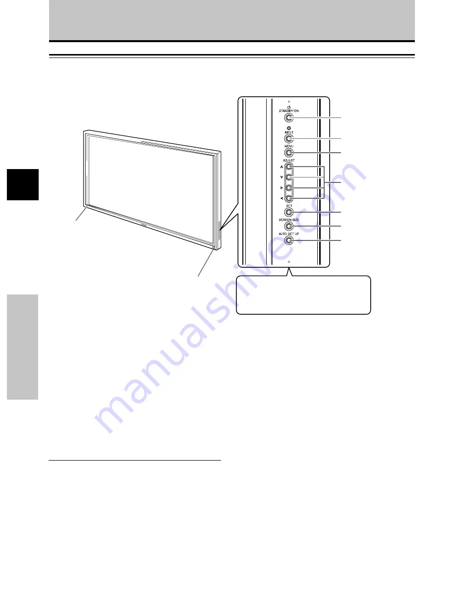
Unidad principal

Unidad principal

1

Sensor del mando a distancia

Oriente el mando a distancia a este sensor para
controlar la unidad (página 6).

2

Indicador STANDBY/ON

Este indicador se enciende en rojo durante el modo de
espera, y cambia a verde cuando la unidad está en
funcionamiento (página 16).
Parpadea en verde cuando la función de gestión de la
alimentación está en funcionamiento (página 20).
El patrón del parpadeo se emplea también para indicar
mensajes de error (página 29).

Panel de operaciones de la unidad principal

3

Botón STANDBY/ON

Púlselo para poner la pantalla en funcionamiento o en
el modo de espera (página 16).

4

Botón INPUT

Púlselo para seleccionar la entrada (página 16).

5

Botón MENU

Púlselo para abrir y cerrar el menú en pantalla (páginas
14 a 26).

6

Botones ADJUST(

5

/

/

3

/

2

)

Utilícelos para navegar por las pantallas de menús y
para realizar diversos ajustes en la unidad.
El empleo de los botones del cursor durante las
operaciones se indica claramente en la visualización
del menú en pantalla (páginas 14 a 26).

7

Botón SET

Púlselo para ajustar o introducir varios ajustes en la
unidad (páginas 14 a 26).

8

Botón SCREEN SIZE

Púlselo para seleccionar el área de pantalla (página
18).

9

Botón AUTO SET

Cuando utilice la entrada de señal de una
computadora, ajusta automáticamente la posición de
la pantalla (POSITION) y el reloj/fase (CLOCK/PHASE)
a los valores óptimos (página 22).

Nota

Cuando se hayan conectado los altavoces

opcionales, el panel de operaciones de la unidad

principal no funcionará.

Unidad principal

Panel de operaciones de la unidad principal

Summary of Contents for CMP5000WXE User m

Page 1: ...or Plasma Display Monitor Model CMP5000WXE READ THE INSTRUCTIONS INSIDE CAREFULLY KEEP THIS USER MANUAL FOR FUTURE REFERENCE For future reference record the serial number of your monitor SERIAL NO The serial number is located on the rear of the monitor MANUAL DE USUARIO ...

Page 2: ...zipiert Wenn andere Videosignale auf diesem Monitor betrachtet werden sollen muss die optionale Videokarte installiert werden Weitere Einzelheiten hierzu erfahren Sie von Ihrem Fachhändler Italiano Questo apparecchio è stato costruito per essere usato come monitor che accompagna un computer Per poter visualizzare su questo schermo segnali video di altro tipo è necessario far uso della scheda video...

Page 3: ...n electric shock If it happens turn off the monitor and disconnect the power plug from the mains and ask service center for instruction Do not put the monitor on an unstable place If you put the monitor on an uneven or unstable place it may fall down and you may be injured Put the monitor on a flat surface strong enough to take the weight Do not apply shock to the monitor Do not use monitor if gla...

Page 4: ...HIS PRODUCT IS SUPPLIED WITH A TWO PIN MAINS PLUG FOR USE IN MAINLAND EUROPE FOR THE U K PLEASE REFER TO THE NOTES ON THIS PAGE IMPORTANT FOR UNITED KINGDOM WORDING FOR CLASS I EQUIPMENT INSTRUCTION BOOKS AND LABELS The mains lead on this equipment is supplied with a molded plug incorporating a fuse the value of which is indicated on the pin face of the plug Should the fuse need to be replaced an ...

Page 5: ...a desk And it may cause injury Do not coil or wind the power cord This may cause excessive heat resulting in a fire Caution for 200 240V operation only This equipment relies on the protective devices in the building installation for short circuit and over current protection Refer to the following table for the suitable number and location of the protective devices which should be provided in the b...

Page 6: ...ing for long but try to refresh them at appropriate intervals of time Turn down the contrast and brightness controls How to clean the monitor Before cleaning the monitor turn off the monitor and disconnect the power plug from the mains When cleaning the monitor do not spray directly the screen or cabinet with cleaner Use a clean dust free dry and soft cloth If it is not enough then use a cloth wit...

Page 7: ...les conditions anormales vous risquez de provoquer un incendie ou de ressentir une secousse électrique Ne laissez pas tomber de l eau ni d autres corps étrangers dans le moniteur Si vous laissez tomber de l eau ou d autres corps étrangers dans le moniteur un incendie peut se produire ou vous pouvez ressentir une secousse électrique Dans le cas où un corps étranger a pénétré dans le moniteur mettez...

Page 8: ...d alimentation conforme aux normes européennes Pour un courant nominal allant jusqu à 6 ampères le cordon d alimentation doit être au moins de type H05VV F3G0 75 mm2 ou H05VVH2 F3G0 75 mm2 UTILISEZ UNIQUEMENT DES PRISES DE TENSION APPROPRIÉE ET RELIÉES À LA TERRE 100 120 V pour les USA le Canada etc 200 240 V pour l Europe etc Ce moniteur se règle automatiquement sur la tension d entrée 100 120 20...

Page 9: ...soit au niveau de la prise murale ATTENTION INSTRUCTIONS DE SÈCURITÈ suite ATTENTION Une secousse électrique et d autres anomalies peuvent provoquer des blessures graves ou des dommages physiques Débranchez la fiche du cordon d alimentation au niveau de la prise secteur quand vous transportez le moniteur Transporter le moniteur sans débrancher la fiche du cordon d alimentation peut endommager le c...

Page 10: ...s des images stationnaires sur l écran pendant trop longtemps mais essayez de les rafraîchir à intervalle régulier Baissez le contraste et la luminosité Comment nettoyer le moniteur Avant de nettoyer le moniteur mettez le hors tension et débranchez la fiche du cordon d alimentation au niveau de la prise secteur Pour nettoyer le moniteur ne vaporisez aucun produit directement sur l écran ni sur le ...

Page 11: ...ie den Netzstecker von der Netzsteckdose ab Rufen Sie dann die Kundendienststelle an Wird der Monitor unter solch anormalen Bedingungen weiterbenutzt besteht Brand oder Stromschlaggefahr Monitor nicht zerlegen oder modifizieren Im Inneren des Monitors befinden sich Hochspannung führende Teile Zerlegung oder Modifizierung des Monitors kann zu einem Brand oder elektrischen Schlag führen Monitor nich...

Page 12: ...MONITOR AUSSCHLIESSLICH AN STECKDOSEN MIT DER RICHTIGEN SPANNUNG UND SICHERHRITSERDUNG 100 120V Für die USA Kanada etc 200 240V Für Europa etc Dieser Monitor paßt sich automatisch an die Eingangsspannung 100 120 200 240V an VORSIXHT BEIM EINSTECKEN DES NETZANSCHLUSSKABELS Bevor Sie den Stecker des Netzanschlußkabels in eine Steckdose mit der richtigen Spannung einstecken vergewissern Sie sich daß ...

Page 13: ... ZU TRENNEN Um eine komplette Tremmung von der Stromquelle zu erreichen entfemen Sie das Netzanschlußkabel vom Monitor oder ziehen es aus der Steckdose Vor dem Transportieren des Monitors den Netzstecker von der Netzsteckdose abziehen Wird der Monitor getragen ohne vorher den Netzstecker von der Netzsteckdose zu trennen kann das Netzkabel beschädigt und ein Brand oder elektrischer Schlag verursach...

Page 14: ...rsuchen Sie die Bilder in angemessenen Zeitintervallen zu erneuern Verringern Sie Kontrast und Helligkeit Reinigung des Monitors Bevor Sie den Monitor reinigen schalten Sie den Monitor aus und ziehen Sie den Netzstecker von der Netzsteckdose ab Sprühen Sie Reinigungsmittel nicht direkt auf den Bildschirm oder das Gehäuse des Monitors Verwenden Sie ein sauberes flusenfreies trockenes und weiches Tu...

Page 15: ...one Smontando o modificando il monitor si possono causare incendi o ricevere scosse elettriche Non utilizzare il monitor in ambienti nei quali è presente acqua Utilizzando il monitor in luoghi nei quali è presente acqua ad esempio il bagno o il locale doccia esso può causare incendi o scosse elettriche Si sconsiglia di utilizzare il monitor in prossimità delle finestre quando piove o nevica e sull...

Page 16: ...ante il funzionamento del monitor o subito dopo il suo spegnimento si possono causare incendi o scosse elettriche dovuti al surriscaldamento del monitor Non disporre il monitor con lo schermo rivolto verso l alto Non mettere il monitor su uno scaffale o in un mobile senza ventilazione adeguata di 4 pollici sopra sotto sul fondo e sul retro Non collocare il monitor su tappeti o materassi Non coprir...

Page 17: ... prima di installare l apparecchiatura RIMUOVERE IL CAVO DI ALIMENTAZIONE PER UN ISOLAMENTO TOTALE Per un distacco totale dalla rete elettrica rimuovere il cavo di alimentazione dalla presa di corrente o dal monitor Protezione Minimo numero di fusibili o di interru ttori automatici Locazione Caso A Apparecchiatura da connettersi a SISTEMI DI POTENZA dotati di presa di terra ben identificabile ecce...

Page 18: ... cercare di aggiornarle a intervalli appropriati di tempo Diminuire il contrasto e la luminosità Pulizia del monitor Prima di pulire il monitor spegnerlo e scollegare la spina dalla presa di corrente Durante le operazioni di pulizia non spruzzare il detergente direttamente sullo schermo o sul mobiletto Utilizzare un panno morbido asciutto e privo di polvere Se ciò non è sufficiente utilizzare un p...

Page 19: ...que el monitor En el interior del monitor hay componentes de alta tensión El desarmado o la modificación del monitor puede producir incendios o descargas eléctricas No utilice el monitor en ambientes húmedos El uso del monitor en un lugar húmedo como en el baño o cerca de una ducha podría causar incendio o descargas eléctricas No se recomienda usar el monitor junto a una ventana cuando está llovie...

Page 20: ...dio o descargas eléctricas debido al calentamiento del monitor No coloque el monitor con el lado de la pantalla hacia arriba No coloque el monitor en un estante o en un cabinete sin que tenga una ventilación adecuada de por lo menos 4 pulgadas en la parte superior lateral inferior y posterior No coloque el monitor sobre una alfombra o un colchón No cubra el monitor con una tela Instrucciones que s...

Page 21: ...Equipamiento para conectar a SISTEMAS DE ALIMENTACIÓN con neutro identificado excepto para Clase C de abajo Fallos de tierra 1 Conductor de fase Sobrecorriente 1 Cualquiera de los dos conductores Caso B Equipamiento para conectar en cualquier suministrador incluyendo SISTEMAS DE ALIMENTACIÓN IT con conectores reversibles excepto para Clase C de abajo Fallos de tierra 2 Ambos conductores Sobrecorri...

Page 22: ... controles de brillo y contraste Limpieza del monitor Antes de limpiar el monitor apague el monitor y desenchúfelo de la toma de corriente Cuando limpie el monitor no rocíe directamente líquidos limpiadores sobre la pantalla o la caja Límpielo con un lienzo limpio sin pelusas seco y suave Si está muy sucio utilice un lienzo humedecido con un detergente sin alcohol y sin amoníaco No raye la superfi...

Page 23: ... the future Notes on Installation Work This product is marketed assuming that it is installed by qualified personnel with enough skill and competence Always have an installation specialist or your dealer install and set up the product HITACHI cannot assume liabilities for damage caused by mistake in installation or mounting misuse modification or a natural disaster Note for Dealers After installat...

Page 24: ...high endurance under conditions of commercial use Improved usability User convenience has been improved by the inclusion of features making the display even more compatible with your computer Some of these include the one touch screen adjustment AUTO SETUP function for computer connections and the POINT ZOOM function to enlarge local portions of the screen image to display important detailed progr...

Page 25: ...m 14 Setup after Connection 14 Operations 16 Selecting an Input Source 16 Screen Size Selection 18 Partial Image Enlargement POINT ZOOM 19 Automatic Power OFF 20 Display Panel Adjustments 21 Adjusting the Picture Quality 21 Adjusting the Image Position and Clock Automatic Adjustment 22 Manual Adjustment of Screen Position and Clock 23 Other Operations 24 Rewriting the Input Display INPUT LABEL 24 ...

Page 26: ...llation of the plasma display and connections to a wide variety of components The section Setting Up the System starting on page 14 covers the necessary on screen menu settings to establish correct linkage between the plasma display and connected components Depending on the connections made this section may or not be necessary The remainder of the sections in this manual is dedicated to the basic ...

Page 27: ...Checking Supplied Accessories Check that the following accessories were supplied 1 Remote control unit 2 AA R6 batteries x 2 3 Speed clamps x 2 4 Bead bands x 2 5 Ferrite core Before Proceeding 6 Cable tie USER S MANUAL 7 Power cord ...

Page 28: ...age 16 4 INPUT button Press to select input page 16 5 MENU button Press to open and close the on screen menu pages 14 to 26 6 ADJUST 5 3 2 buttons Use to navigate menu screens and to adjust various settings on the unit Usage of cursor buttons within operations is clearly indicated in the on screen display pages 14 to 26 7 SET button Press to adjust or enter various settings on the unit pages 14 to...

Page 29: ...size page 18 2 INPUT buttons Use to select the input page 16 3 MENU button Press to open and close the on screen menu pages 14 to 26 4 ADJUST 5 3 2 buttons Use to navigate menu screens and to adjust various settings on the unit Usage of cursor buttons within operations is clearly indicated at the bottom the on screen menu display pages 14 to 26 5 SET button Press to adjust or enter various setting...

Page 30: ...uter PC or similar component Make sure that the connection made corresponds to the format of the signal output from the connected component pages 9 to 11 If you are having difficulty with operation of the remote control unit The remote control unit may not operate if there are objects placed between it and the display Operational distance will gradually become shorter as the batteries begin to wea...

Page 31: ...put impedance of the component s synchronization signal is below 75 Ω set this switch to the 75 Ω position pages 9 10 9 AUDIO INPUT Stereo mini jack Use to obtain sound when INPUT1 or INPUT2 is selected Connect the audio output jack of components connected to INPUT1 or INPUT2 to this unit page 11 0 AUDIO OUTPUT Stereo mini jack Use to output the audio of the selected source component connected to ...

Page 32: ...be used are shown in the diagram below Be sure to attach in 4 or more locations above and below left and right of the center line Use bolts that are long enough to be inserted 12 mm to 18 mm into the main unit from the attaching surface for both a holes and b holes Refer to the side view diagram below As this unit is constructed with glass be sure to install it on a flat unwarped surface CAUTION B...

Page 33: ...s jack Connection to a personal computer Connection method differs depending on the computer type When connecting please thoroughly read the computer s instruction manual Before making connections be sure to make sure that the personal computer s power and this unit s main power is off For the PC input signals and screen sizes that this unit is compatible with please refer to supplement 1 page 31 ...

Page 34: ... INPUT1 OUTPUT With this unit it is possible to output the video signal to an external monitor or other component from the OUTPUT INPUT1 terminal Note A video signal will not be output from the OUTPUT INPUT1 terminal when the main power of this unit is off or in standby To an external monitor Connection of SYNC ON G analog RGB source Make SYNC ON G connections for a personal computer with output t...

Page 35: ...nt s power and the unit s main power is off Connecting the speakers This unit is equipped with speaker output terminals for connection to the speaker system not supplied specially designed for use with this unit Refer to the illustrations below when making connections to the speaker terminals on this unit 10 mm Note When making speaker connections be sure to match the polarities and of the speaker...

Page 36: ...efficiency protection Always be sure to connect the power cord to a three pronged grounded outlet and make sure that the cord is properly grounded If you use a power source converter plug use an outlet with a ground terminal and screw down the ground line Attaching the Ferrite Core To help prevent noise attach the accessory ferrite core to the plug end of the power cord as shown in the accompanyin...

Page 37: ...eed clamps are designed to be difficult to undo once in place Please attach carefully To attach the speed clamps to the main unit Connect the speed clamps using the 4 holes marked with Black dot below depending on the situation As viewed from the rear of the display Installation and Connections 1 2 To remove speed clamps Using pliers twist the clamp 90 and pull it outward In some cases the clamp m...

Page 38: ...ollow the procedure described below and make settings as they apply to the type of components connected Screen Mode setup Note These settings are required only when using the following input signal refresh rates 1 31 5 kHz horizontal 60 Hz vertical 2 48 4 kHz horizontal 60 Hz vertical or 56 5 kHz horizontal 70 Hz vertical No manual setup is necessary for signals with other refresh rates since adju...

Page 39: ... A I NP UT I NP UT 1 L E B L A MAIN MENU INPUT1 3 Press 5 to select CLAMP POSITION SELECT CHANGE EXIT SET MENU PICTURE SCREEN SET UP OPTION NT S E T T I N CL AMP POWE R G OF F P S I T I ON O M NAGEME A I NP UT I NP UT 1 L E B L A V GA A U TO MAIN MENU INPUT1 4 Press SET to select LOCKED SELECT CHANGE EXIT SET MENU PICTURE SCREEN SET UP OPTION NT S E T T I N CL AMP POWE R G OF F P S I T I ON O M NA...

Page 40: ...nal input will cause the menu screen to turn off If the input computer signal is not supported by the display the following message will be displayed 0 8 5 5 1 2 6 8 4 k H z f V 1 7 1 7 H z f H P O U SUP N S R ED T I NAL G CAU I O N T FUL L I NPUT 1 X 0 2 0 k H z f V 7 7 1 5 H z f H T OU N O A R F G E CAU I O N T FUL L I NPUT 1 4 Use VOLUME on the remote control unit to adjust the volume If no aud...

Page 41: ...tomatically canceled about 8 minutes after the button is pressed and the volume level is adjusted to the minimum level Press VOLUME or VOLUME to adjust the volume at a desired level To confirm display settings DISPLAY Press DISPLAY on the remote control unit The currently selected input screen size and refresh rates will be displayed for about 3 seconds O D BY T DOT I NPUT 1 0 6 0 4 6 0 8 4 0 k H ...

Page 42: ...en sizes described in the table on this page Press SCREEN SIZE to select the size The screen size changes each time SCREEN SIZE is pressed as follows Consult the table Computer Signal Formats Supported page 31 for information regarding screen sizes supported by each signal format Notes When the PARTIAL or FULL setting is used to display a non wide screen 4 3 picture fully on a wide screen a portio...

Page 43: ...aken for three seconds or more the display screen will disappear SET or 5 2 3 can be pressed again if desired to change the zoom ratio or display position 4 Press the remote control unit s POINT ZOOM once again to cancel the point zoom operation The point zoom function will also be canceled whenever the input signal changes the menu screen is displayed or the INPUT changes Note Whenever point zoom...

Page 44: ...O S E T T I N CL AMP POWE R G OF F P S I T I ON O M NA GEME A I NP UT I NP UT 1 L E B L A V GA NT MAIN MENU INPUT1 When using INPUT 2 PICTURE SCREEN SET UP OPTION V GA AU T O S E T T I N CL AMP A UTO POWE R G OF F OF F P S I T I ON O I NP UT I NP UT 2 L E B L A MAIN MENU INPUT2 4 Press SET to confirm selection of the POWER MANAGEMENT or AUTO POWER OFF When OFF is selected the display will continue...

Page 45: ...s PICTURE mode adjustment items Below are brief descriptions of the options that can be set in the PICTURE mode CONTRAST Adjust according to the surrounding brightness so that the picture can be seen clearly BRIGHT Adjust so that the dark parts of the picture can be seen clearly R LEVEL Adjust the amount of red in the picture G LEVEL Adjust the amount of green in the picture B LEVEL Adjust the amo...

Page 46: ...erform this adjustment individually for each input function INPUT 1 INPUT 2 and each signal type Press AUTO SET UP on either the main unit or remote control unit Optimum settings may not be possible for low luminance and certain other kinds of signals In this case following the instructions in the following section Manual Adjustment of Screen Position and Clock to make more precise adjustments AUT...

Page 47: ...ow are brief descriptions of the options that can be set in the SCREEN mode POSITION H POSITION Adjust the picture s position to the left or right V POSITION Adjust the picture s position upward or downward CLOCK PHASE CLOCK Adjust letter breakup or noise on the screen This setting adjusts the unit s internal clock signal frequency that corresponds to the input video signal PHASE Adjust so that th...

Page 48: ...E B L A T E S RE D N E A E C A S P MAIN MENU INPUT1 5 Press 2 3 5 to select the first desired character here C then press SET to confirm repeat this step to input up to eight desired characters SELECT SET EXIT SET MENU BACK SPACE J M K L B C D E F G H W Z X Y N O P Q R S T V U 9 0 1 2 3 4 5 6 8 7 I NP UT I NP UT 1 L E B L A T E S RE E C A S P D N E A C I MAIN MENU INPUT1 Usable characters include ...

Page 49: ...D setting but at a even lower levels of power consumption MODE 2 fixes the screen brightness regardless of the input signal This is effective at reducing panel deterioration due to screen burning 4 Following completion of settings press MENU to return to normal screen display Note The POWER CONTROL setting affects all input sources AUTO FUNCTION This display is equipped with an optional AUTO FUNCT...

Page 50: ...DIO OUT The signal level produced at the AUDIO OUT jack can be set to FIXED or VARIABLE linked to the VOLUME as desired 1 Press MENU The onscreen menu will be displayed MAIN MENU INPUT1 SELECT ENTER EXIT SET MENU PICTURE SCREEN SET UP OPTION 0 6 0 6 0 6 0 0 0 CONT RAST 0 BR R L EV EL I GHT G L EV EL B L EV EL H E NHANCE V E NHANCE R S ET E 2 Press 2 3 to select OPTION SELECT CHANGE EXIT SET MENU P...

Page 51: ...bleshooting What may at first seem to be an malfunction may be remedied with a quick check Please check to see if a warning is displayed on the screen If displayed refer to the table below and check the mode If there is no display check to see if the problem is listed on page 28 The problem may also be caused by something other than this unit so please also check the other components being used su...

Page 52: ...tions of image appear to be losing intensity Speckles or noise appears on screen Stripes appear on the screen Operation is not possible Sound is heard from inside the unit Fan isn t moving Fan speed changes Check the input signal compatibility chart page 31 Is the correct screen size selected pages 18 22 and 23 Adjust using SCREEN mode on the menu screen page 23 If there is still no improvement th...

Page 53: ...he problem persists disconnect the power plug and consult your dealer or a service center When STANDBY ON is pressed to set the unit to the standby mode the indicator will flash red for several seconds page 16 Other than this if the power turns off by itself or refuses to turn on or if the red indicator conditions flashing a malfunction may be indicated Immediately disconnect the power plug and co...

Page 54: ... Plug Play VESA DDC1 2B Output Mini D sub 15 pin socket connector 75 Ω with buffer INPUT 2 Input BNC jack x5 RGB signal SYNC ON G compatible RGB 0 7 Vp p 75 Ω no sync HD CS VD TTL level positive and negative polarity 75 Ω or 2 2 kΩ impedance switch SYNC ON G 1 Vp p 75 Ω negative sync Additional Information Audio Input AUDIO INPUT for INPUT 1 2 Stereo mini jack L R 500mVrms more than 10 kΩ Output A...

Page 55: ...1kHz 46 9kHz 53 7kHz 49 7kHz 31 7kHz 48 4kHz 56 5kHz 60 0kHz 60 2kHz 68 7kHz 53 7kHz 64 9kHz 67 7kHz 68 7kHz 61 8kHz 71 7kHz 45 1kHz 48 4kHz 55 5kHz 60 0kHz 64 0kHz 80 0kHz 91 1kHz 75 0kHz 81 3kHz 87 5kHz 93 8kHz 106 3kHz 1024x768 1024x768 1024x768 1024x768 1016x768 984x768 1024x768 960x768 1024x768 640x480 800x600 832x624 852x480 1024x768 1280x768 4 3 NEC PC 9800 NEC PC 9800 852x480 864x480 Apple...

Page 56: ...ine resolution Supplement 2 Signal assignment of INPUT 1 Mini D sub 15 pin socket connector Input Output 1 2 3 4 5 6 7 8 9 10 11 12 13 14 15 R or CR PR G or Y B or CB PB NC No connection GND GND GND GND DDC 5V GND NC No connection DDC SDA HD or H V SYNC VD DDC SCL NC No connection NC No connection NC No connection Pin No Apple and Macintosh are registered trademarks of Apple Computer Inc Microsoft...

Page 57: ...utile à l avenir Remarques sur l installation Ce produit est vendu en assumant qu il sera installé par un personnel suffisamment expérimenté et qualifié Faites toujours réaliser le montage et l installation par un spécialiste ou par votre revendeur HITACHI ne peut être tenu responsable pour tout dommage causé par une erreur d installation ou de montage une mauvaise utilisation ou un désastre natur...

Page 58: ...lusion de fonctions qui rendent l écran encore plus compatible avec votre ordinateur Citons la fonction AUTO SETUP configuration automatique de réglage simplifié pour les branchements sur l ordinateur et la fonction POINT ZOOM agrandissement partiel de l image permettant d afficher les détails précis d une image sur l écran Économie d énergie Cet écran consomme le moins de courant de tous les écra...

Page 59: ...ise en œuvre après raccordement 14 Fonctionnement 16 Choix de la source 16 Choix du format de l image 18 Agrandissement partiel de l image POINT ZOOM 19 Mise hors tension automatique 20 Réglages de l écran à plasma 21 Réglage de la qualité de l image 21 Réglage automatique de la position de l image et de l horloge 22 Réglage manuel de la position d écran et de l horloge 23 Autres démarches 24 Modi...

Page 60: ...art sont rédigés en tenant compte des possibilités de la télécommande à moins que la touche ou la commande ne soient présentes que sur l écran à plasma A noter qu une touche ou une commande de l écran à plasma ayant le même nom qu une touche ou une commande de la télécommande jouent les mêmes rôles Ce qui suit est un exemple de démarches réelles expliquant comment ajuster la position verticale et ...

Page 61: ...es fournis Assurez vous que les accessoires suivants font partie de la fourniture 1 Boîtier de télécommande 2 2 piles AA R6 3 2 colliers rapides 4 2 serre câble 5 Noyau en ferrite Avant de commencer 6 Attache de câble 7 Cordon d alimentation MANUEL UTILISATEUR ...

Page 62: ...ouche pour choisir le signal d entrée page 16 5 Touche MENU Appuyez sur cette touche pour ouvrir ou fermer les menus s affichant sur l écran pages 14 à 26 6 Touche ADJUST 5 3 2 Utilisez ces touches pour naviguer dans les menus et choisir des valeurs de réglage L usage de ces touches est clairement indiqué sur les pages de menu affichées sur l écran pages 14 à 26 7 Touche SET Appuyez sur cette touc...

Page 63: ... touches pour régler le niveau d écoute page 17 Les différents organes et leurs rôles 8 9 7 0 2 3 4 5 6 1 ATTENTION Veillez à respecter les indications de polarité et gravées dans le logement des piles N utilisez pas tout à la fois une pile neuve et une pile usagée Remplacez les deux piles en même temps Certaines piles identiques par leur taille diffèrent par leur tension N utilisez pas deux types...

Page 64: ...T1 lorsque l écran à plasma est hors tension ou en veille page 10 7 INPUT2 prises BNC Utilisez ces prises pour le branchement d un ordinateur personnel PC ou d un appareil similaire Choisissez la prise en fonction de la nature du signal fourni par l appareil connecté pages 9 à 11 En cas de difficulté à l emploi de la télécommande La télécommande risque de ne pas fonctionner si son faisceau est int...

Page 65: ...t inférieure à 75 Ohms placez ce sélecteur sur la position 75 Ω pages 9 et 11 9 AUDIO INPUT Mini prise stéréo Utilisez cette prise pour disposer des sons appliqués sur INPUT1 ou INPUT2 Branchez sur cette prise la sortie son de l appareil relié à INPUT1 ou INPUT2 page 11 0 AUDIO OUTPUT Mini prise stéréo Utilisez cette sortie pour appliquer à un amplificateur audiovisuel ou un appareil similaire les...

Page 66: ...s minimum placés au dessus et au dessous de l axe horizontal et à droite et à gauche de l axe vertical Dans le cas des perçages a et b utilisez des boulons dont la longueur est telle qu ils pénètrent dans l écran à plasma de 12 mm au moins et de 18 mm au plus Reportez vous à la vue de côté ci dessous L écran à plasma est muni d une vitre qui interdit sa pose sur une surface qui n est pas plane ATT...

Page 67: ...dinateur personnel La méthode de raccordement dépend du type de l ordinateur Avant d effectuer les raccordements veuillez lire attentivement le mode d emploi de l ordinateur Avant tout raccordement veillez à ce que l écran à plasma et l ordinateur soient tous deux hors tension Pour les signaux d entrée PC et les tailles d écran avec lesquelles cet appareil est compatible reportez vous au supplémen...

Page 68: ... le signal vidéo puisse être appliqu à un moniteur ou un autre appareil à partir de la prise OUTPUT INPUT1 Remarque Le signal vidéo n est pas présent sur la prise OUTPUT INPUT1 lorsque l écran à plasma est hors tension ou en veille Vers un moniteur extérieur Raccordement d une source analogique RVB fournissant le signal de synchronisation sur le vert G ON SYNC Raccordement d une source analogique ...

Page 69: ... SYNC Voir page 10 Raccordements audio Avant tout raccordement veillez à ce que les appareils soient tous deux hors tension Raccordement des enceintes Cet écran à plasma est doté de prises de sortie pour enceintes acoustiques non fournies qui ont été spécialement conçues pour fonctionner avec l écran Avant d effectuer un raccordement reportez vous aux illustrations 10 mm Remarque Veillez à ne pas ...

Page 70: ...eurs plus un conducteur de masse Veillez à ce que la prise possède une broche de mise à la terre et qu elle soit convenablement câblée En cas d utilisation d un adaptateur le conducteur de masse doit tout de même être relié à la terre Fixation du noyau du ferrite Pour éviter les parasites fixez le noyau en ferrite fourni comme accessoire sur le bout à fiche du cordon d alimentation comme indiqué s...

Page 71: ...liers rapides sont conçus pour que l ouverture soit difficile Fermez les soigneusement Fixation des colliers rapides à l écran à plasma Engagez les colliers rapides dans les trous 4 repérés par sur l illustration ci dessous Pour retirer les colliers rapides A l aide d une pince tordez le collier de 90 puis tirez le vers vous Avec le temps le collier peut se détériorer et il peut être nécessaire de...

Page 72: ... La page de menu s affiche MAIN MENU INPUT1 SELECT ENTER EXIT SET MENU PICTURE SCREEN SET UP OPTION 0 6 0 6 0 6 0 0 0 CONT RAST 0 BR R L EV EL I GHT G L EV EL B L EV EL H E NHANCE V E NHANCE R S ET E 5 Utilisez les touches 2 3 pour choisir l option SET UP SELECT ENTER EXIT SET MENU PICTURE SCREEN SET UP OPTION V GA NT AU T O S E T T I N CL AMP POWE R G OF F P S I T I ON O M NAGEME A I NP UT I NP U...

Page 73: ...I NP UT I NP UT 1 L E B L A MAIN MENU INPUT1 3 Utilisez les touches 5 pour choisir l option CLAMP POSITION SELECT CHANGE EXIT SET MENU PICTURE SCREEN SET UP OPTION NT S E T T I N CL AMP POWE R G OF F P S I T I ON O M NAGEME A I NP UT I NP UT 1 L E B L A V GA A U TO MAIN MENU INPUT1 4 Appuyez sur la touche SET pour choisir LOCKED SELECT CHANGE EXIT SET MENU PICTURE SCREEN SET UP OPTION NT S E T T I...

Page 74: ... suit l entrée Si la page de menu est affichée elle disparaît lorsque le signal d entrée est modifié Si le signal fourni par l ordinateur n est pas accepté par cet écran le message suivant est affiché 0 8 5 5 1 2 6 8 4 k H z f V 1 7 1 7 H z f H P O U SUP N S R ED T I NAL G CAU I O N T FUL L I NPUT 1 X 0 2 0 k H z f V 7 7 1 5 H z f H T OU N O A R F G E CAU I O N T FUL L I NPUT 1 4 Utilisez les touc...

Page 75: ... sons est automatiquement abandonnée environ 8 minutes après une action sur cette touche les sons sont rétablis au niveau minimum Utilisez les touches VOLUME ou VOLUME pour régler le niveau d écoute Pour vérifier les réglages DISPLAY Appuyez sur la touche DISPLAY de la télécommande Le nom de l entrée choisie le format de l image et les fréquences de rafraîchissement seront affichés pendant 3 secon...

Page 76: ...ction aux droits d auteur protégés par la législation Lorsque le mode d écran DOT BY DOT ou 4 3 est sélectionné la position d affichage est légèrement décalée à chaque mise sous tension afin d éviter une rémanence de l image sur l écran Changement de la position de l image La position sur l écran peut être choisie à l aide des touches 5 y compris dans le cas du format PARTIAL lorsque le signal d e...

Page 77: ...est prise pendant 3 secondes ou plus l écran d affichage disparaît Au besoin vous pouvez appuyer à nouveau sur SET ou les touches 5 2 3 pour modifier le taux de zoom ou la position de la zone affichée 4 Appuyez une nouvelle fois sur la touche POINT ZOOM de la télécommande annule l agrandissement partiel de l image La fonction d agrandissement partiel de l image sera annulée également si le signal ...

Page 78: ... EXIT SET MENU PICTURE SCREEN SET UP OPTION AU T O S E T T I N CL AMP POWE R G OF F P S I T I ON O M NA GEME A I NP UT I NP UT 1 L E B L A V GA NT MAIN MENU INPUT1 A l emploi de la prise INPUT 2 PICTURE SCREEN SET UP OPTION V GA AU T O S E T T I N CL AMP A UTO POWE R G OF F OF F P S I T I ON O I NP UT I NP UT 2 L E B L A MAIN MENU INPUT2 4 Appuyez sur SET pour valider la sélection POWER MANAGEMENT...

Page 79: ... qui peuvent être réglés Voici de brèves explications sur les paramètres qui peuvent être réglés grâce à l option PICTURE CONTRAST Réglez le contraste en fonction de l éclairage ambiant de manière que l image soit bien visible BRIGHT Réglez la luminosité de manière que les parties sombres de l image soient bien visibles R LEVEL Pour régler la quantité de rouge dans l image G LEVEL Pour régler la q...

Page 80: ...ce réglage individuellement pour chaque fonction d entrée INPUT 1 et INPUT 2 et pour chaque type de signal Appuyez sur la touche AUTO SET UP de l appareil ou de la télécommande Des ajustements optimaux peuvent s avérer impossibles avec des signaux à faible luminance ou d autres types de signaux Dans ce cas passez à la section suivante Réglage manuel de la position d écran et de l horloge pour effe...

Page 81: ...que entrée INPUT1 à INPUT2 et chaque signal Paramètres qui peuvent être réglés Voici de brèves explications sur les paramètres qui peuvent être réglés grâce à l option SCREEN POSITION H POSITION Réglage de la position latérale de l image V POSITION Réglage de la position verticale de l image CLOCK PHASE CLOCK Réglage des signaux et du bruit Ce réglage agit sur la fréquence du signal de l horloge i...

Page 82: ... C A S P MAIN MENU INPUT1 5 Servez vous des touches 2 3 5 pour choisir le premier caractère C dans ce cas puis appuyez sur SET pour valider Répétez cette démarche pour saisir jusqu à 8 caractères au maximum SELECT SET EXIT SET MENU BACK SPACE J M K L B C D E F G H W Z X Y N O P Q R S T V U 9 0 1 2 3 4 5 6 8 7 I NP UT I NP UT 1 L E B L A T E S RE E C A S P D N E A C I MAIN MENU INPUT1 Les caractère...

Page 83: ... de la même façon que le réglage STANDARD mais à un niveau de consommation de courant encore plus bas Lorsque MODE 2 est sélectionné la luminosité de l écran est fixe quel que soit le signal d entrée ce qui est efficace pour réduire la détérioration de l écran par rémanence d image 4 Une fois terminés ces réglages appuyez sur la touche MENU pour repasser à l écran normal Remarque Le paramètre POWE...

Page 84: ... du signal fourni à la prise AUDIO OUT peut être réglé sur FIXED ou VARIABLE lié à la fonction VOLUME 1 Appuyez sur la touche MENU La page de menu est affichée MAIN MENU INPUT1 SELECT ENTER EXIT SET MENU PICTURE SCREEN SET UP OPTION 0 6 0 6 0 6 0 0 0 CONT RAST 0 BR R L EV EL I GHT G L EV EL B L EV EL H E NHANCE V E NHANCE R S ET E 2 Utilisez les touches 2 3 pour choisir OPTION SELECT CHANGE EXIT S...

Page 85: ...comme une anomalie de fonctionnement Si une indication est affichée sur l écran consultez le tableau ci dessous Dans le cas contraire et si vous pensez que cet appareil est défectueux procédez aux vérifications de la page 28 Il peut arriver aussi que le défaut provienne d un autre élément de l installation assurez vous que ce n est pas le cas Si en dépit de ces contrôles vous n êtes pas en mesure ...

Page 86: ...affichés sont déformés Un son aigu est parfois émis par l écran à plasma Les portions lumineuses de l image semblent manquer d intensité Les taches ou du bruit se forment sur l écran Des rayures se forment sur l écran Le fonctionnement n est pas possible L écran à plasma émet des bruits Le ventilateur ne fonctionne pas Changement de vitesse du ventilateur Vérifiez la compatibilité du signal d entr...

Page 87: ...i le problème subsiste débranchez la fiche du cordon d alimentation et consultez votre revendeur ou un centre de service Si vous appuyez sur le bouton STANDBY ON pour mettre l appareil en mode Veille le voyant clignote en rouge pendant quelques secondes page 16 Par ailleurs si l alimentation est coupée d elle même si l appareil ne peut pas être mis sous tension ou si le voyant rouge clignote il pe...

Page 88: ...g Play VESA DDC1 2B Sortie Mini D sub 15 broches connecteur femelle 75 Ohms avec tampon Entrée 2 Entrée Prise BNC x 5 Signal RVB Compatible G ON SYNC RVB 0 7 Vcc 75 Ohms pas de synchro HD CS VD Niveau TTL polarités positive et négative 75 Ohms ou 2 2 kOhms commutateur d impédance G ON SYNC 1 0 Vcc 75 Ohms synchro négative Audio Entrée Entrée audio pour Entrée 2 1 Mini fiche stéréo G D 500 mV eff p...

Page 89: ...FULL PARTIAL Remarques 640x400 640x480 800 x600 832x624 852x480 1024x768 1152x864 1152x870 1152x900 1280x768 1280x960 1280x1024 1600 x 1200 Format d image points x lignes Horizontal 1280x768 1280x768 1280x768 1280x768 1280x768 1280x768 1280x768 1280x768 1280x768 1280x768 1280x768 1280x768 24 8 kHz 31 5 kHz 31 5 kHz 35 0 kHz 37 9 kHz 37 5 kHz 43 3 kHz 35 2 kHz 37 9 kHz 48 1 kHz 46 9 kHz 53 7 kHz 49...

Page 90: ...lignes Supplément 2 Bornage de INPUT1 connecteur mini D sub 15 broches Entrée Sortie 1 2 3 4 5 6 7 8 9 10 11 12 13 14 15 R ou CR PR G ou Y B ou CB PB Réservé pas de connexion Masse Masse Masse Masse DDC 5 V Masse Réservé pas de connexion DDC SDA HD ou H V SYNC VD DDC SCL Réservé pas de connexion Réservé pas de connexion Réservé pas de connexion Numéro de broche Apple et Macintosh sont des marques ...

Page 91: ...nahme griffbereit auf Hinweis zur Installation Dieses Produkt ist für die Installation durch einen Fachmann bestimmt Der Käufer muss dieses Produkt entweder von einem qualizifierten Techniker oder vom Fachhändler installieren und einrichten lassen HITACHI übernimmt keinerlei Haftung für Schäden die auf unsachgemäße Installation oder Befestigung zweckentfremdeten Gebrauch Nachgestaltung oder Naturk...

Page 92: ...zu begrenzen und die Ventilator Drehzahl automatisch Änderungen der Umgebungstemperatur anzupassen Derartige Einrichtungen tragen zu einer hohen Betriebssicherheit und Widerstandsfähigkeit des Displays beim kommerziellen Einsatz bei Erhöhter Bedienungskomfort Verschiedene Funktionen zur Steigerung des Bedienungskomforts erleichtern den Betrieb dieses Displays in Verbindung mit einem Personalcomput...

Page 93: ...m Anschließen 14 Bedienung 16 Wahl einer Eingangssignalquelle 16 Wahl des Bildschirmformats 18 Vergrößerung eines Bildausschnitts POINT ZOOM 19 Abschaltautomatik 20 Display Einstellungen 21 Einstellen der Bildqualität 21 Einstellen von Bildposition und Taktsignal automatische Einstellung 22 Manuelle Einstellung von Bildposition und Taktsignal 23 Weitere Funktionen 24 Neuschreiben der Eingangskennz...

Page 94: ...14 beginnende Abschnitt Setup des Systems erläutert die Einstellungen der in den Bildschirm eingeblendeten Menüs die zur Herstellung einer korrekten Verbindung zwischen Plasma Display und den daran angeschlossenen Geräten erforderlich sind Abhängig von den jeweils vorgenommenen Anschlüssen kann dieser Abschnitt u U übergangen werden Die übrigen Abschnitte dieser Anleitung enthalten Erläuterungen d...

Page 95: ...ten Zubehörs Bitte vergewissern Sie sich nach dem Auspacken dass die nachstehend aufgeführten Zubehörteile vollständig vorhanden sind 1 Fernbedienung 2 Mignonzelle R6 Größe AA x 2 3 Schnellverschluss Kabelband x 2 4 Kugelband x 2 5 Ferritkern 6 Kabelband 7 Netzkabel BEDIENUNGSANLEITUNG ...

Page 96: ...ge in den Bildschirm eingeblendet und wieder vom Bildschirm gelöscht Seite 14 bis 26 6 ADJUST 5 2 3 Einstelltasten Diese Tasten dienen zum Navigieren in den verschiedenen Menüs und zum Ändern von Einstellungen Wenn diese Tasten bei bestimmten Bedienungsvorgängen als Cursortasten zu betätigen sind wird dies klar erkennbar am unteren Rand der Menüanzeige dargestellt Seite 14 bis 26 7 SET Eingabetast...

Page 97: ...en dieser Taste kann ein gewünschter Bildausschnitt vergrößert werden Seite 19 VOLUME Lautstärke Regeltasten Diese Tasten dienen zur Einstellung des Lautstärkepegels Seite 17 Bezeichnungen und Funktionen der Teile Einlegen der Batterien in die Fernbedienung Den Deckel leicht eindrücken und zum Abnehmen in Pfeilrichtung schieben 2 Mignonzellen R6 Größe AA VORSICHT Legen Sie die Batterien polaritäts...

Page 98: ...ys ausgeschaltet ist oder sich dieses im Bereitschaftszustand befindet Seite 10 wird das Videosignal nicht von der Buchse OUTPUT INPUT1 ausgegeben Anschlussleiste 7 m Fernbedienungs Signalsensor 30 30 Mögliche Probleme beim Gebrauch der Fernbedienung Falls sich ein Hindernis zwischen der Fernbedienung und dem Plasma Display befindet arbeitet die Fernbedienung u U nicht Bei abnehmender Batteriespan...

Page 99: ...g INPUT1 oder INPUT2 gewählt ist Verbinden Sie diese Buchse mit der Audio Ausgangsbuchse des an INPUT1 oder INPUT2 des Plasma Displays angeschlossenen Gerätes Seite 11 0 AUDIO OUTPUT Stereo Minibuchse Audio Ausgang Von dieser Buchse kann das Tonsignal der gewählten an das Plasma Display angeschlossenen Signalquelle an einen AV Verstärker oder ein ähnliches Gerät ausgegeben werden Seite 11 MAIN POW...

Page 100: ...ts daneben zu befestigen Verwenden Sie Schrauben die lang genug sind um von der Montagefläche aus um 12 18 mm in Bohrung a und b eingeschoben werden zu können Siehe das Schema rechts unten Seitenansicht Da dieses Plasma Display Bauteile aus Glas enthält muss es an einer flachen ebenen Oberfläche montiert werden VORSICHT Das Gewicht des Plasma Displays von ca 40 kg und seine geringe Tiefe machen da...

Page 101: ...ssverfahren ist je nach Ausführung des Personalcomputers verschieden Bitte schlagen Sie vor dem Anschließen in der Bedienungsanleitung Ihres PC nach Vergewissern Sie sich dass die Stromzufuhr des Personalcomputers und der MAIN POWER Schalter des Plasma Displays ausgeschaltet sind bevor Sie irgendwelche Anschlüsse herstellen Informationen zu den PC Eingangssignalen und den Bildschirmformaten mit de...

Page 102: ... RGB INPUT1 OUTPUT Bei diesem Plasma Display besteht die Möglichkeit das Videosignal von der Buchse OUTPUT INPUT1 an einen externen Monitor oder ein anderes Gerät auszugeben Hinweis Wenn der MAIN POWER Schalter des Plasma Displays ausgeschaltet ist oder sich dieses im Bereitschaftszustand befindet wird das Videosignal nicht von der Buchse OUTPUT INPUT1 ausgegeben An externen Monitor Anschluss eine...

Page 103: ... den auf der vorigen Seite gezeigten G ON SYNC Anschluss her INPUT1 INPUT2 Audio Eingangsbuchsen Tonsignalausgabe Stereo Minibuchse L R Der Ton der gewählten Video Eingangsquelle liegt an den folgenden Buchsen an SPEAKER Klemmen Stereo Minibuchsen L R Audio Anschlüsse Vergewissern Sie sich dass die Stromzufuhr der Audio Komponente und der MAIN POWER Schalter des Plasma Displays ausgeschaltet sind ...

Page 104: ...die Gefahr von Brand und elektrischem Schlag Aus Sicherheitsgründen muss ein dreiadriges Netzkabel mit Erdungspol für dieses Plasma Display verwendet werden Achten Sie stets darauf das Netzkabel an eine vorschriftsmäßig geerdete dreipolige Netzsteckdose anzuschließen damit eine einwandfreie Erdung des Kabels gewährleistet ist Bei Verwendung eines Umrüststeckers ist das Netzkabel an eine Netzsteckd...

Page 105: ...legt dass sie nach dem Anbringen nur noch schwer gelöst werden können Gehen Sie daher bei der Befestigung sorgfältig vor Befestigen der Schnellverschluss Kabelbänder am Plasma Display Verwenden Sie die vier in der nachstehenden Abbildung mit gekennzeichneten Löcher um die Schnellverschluss Kabelbänder nach Bedarf am Plasma Display zu befestigen Entfernen der Schnellverschluss Kabelbänder Drehen Si...

Page 106: ...auf dem Bildschirm MAIN MENU INPUT1 SELECT ENTER EXIT SET MENU PICTURE SCREEN SET UP OPTION 0 6 0 6 0 6 0 0 0 CONT RAST 0 BR R L EV EL I GHT G L EV EL B L EV EL H E NHANCE V E NHANCE R S ET E 5 Betätigen Sie 2 3 zur Wahl von SET UP SELECT ENTER EXIT SET MENU PICTURE SCREEN SET UP OPTION V GA NT AU T O S E T T I N CL AMP POWE R G OF F P S I T I ON O M NAGEME A I NP UT I NP UT 1 L E B L A MAIN MENU ...

Page 107: ...NP UT 1 L E B L A MAIN MENU INPUT1 3 AUTO LOCKED 2 3 Betätigen Sie 5 zur Wahl von CLAMP POSITION SELECT CHANGE EXIT SET MENU PICTURE SCREEN SET UP OPTION NT S E T T I N CL AMP POWE R G OF F P S I T I ON O M NAGEME A I NP UT I NP UT 1 L E B L A V GA A U TO MAIN MENU INPUT1 4 Drücken Sie SET zur Wahl von LOCKED SELECT CHANGE EXIT SET MENU PICTURE SCREEN SET UP OPTION NT S E T T I N CL AMP POWE R G O...

Page 108: ...an eine Menüanzeige erscheint verschwindet diese vom Bildschirm wenn auf einen anderen Eingang umgeschaltet wird Wenn das von einem Personalcomputer zugeleitete Signal nicht von diesem Plasma Display unterstützt wird erscheint die folgende Fehlermeldung auf dem Bildschirm 0 8 5 5 1 2 6 8 4 k H z f V 1 7 1 7 H z f H P O U SUP N S R ED T I NAL G CAU I O N T I NPUT 1 X 0 2 0 k H z f V 7 7 1 5 H z f H...

Page 109: ...tomatisch wieder aufgehoben wonach die Lautstärke auf den Minimalpegel eingestellt wird Betätigen Sie anschließend VOLUME oder VOLUME um die gewünschte Lautstärke einzustellen Überprüfen der Anzeigeparameter DISPLAY Drücken Sie DISPLAY an der Fernbedienung Danach werden der momentan gewählte Eingang das aktuelle Bildschirmformat sowie Horizontal und Vertikalfrequenz des Eingangssignals ca 3 Sekund...

Page 110: ...er FULL Modus verletzt werden können Bei Wahl des Bildschirmformats DOT BY DOT oder 4 3 verschiebt sich die Anzeigeposition automatisch bei jedem Einschalten der Stromzufuhr geringfügig um ein Einbrennen des Bilds zu verhindern Verschieben der Bildposition nach oben oder unten Wenn das Signal eines Personalcomputers nur 1280 x 1024 60 Hz zugeleitet wird kann die Anzeigeposition selbst bei Wahl der...

Page 111: ...r vergrößerte Bildausschnitt nach oben unten links oder rechts verschoben werden Wenn innerhalb von 3 Sekunden kein Bedienungsvorgang stattfindet kehrt das Bild auf den Bildschirm zurück Um den Vergrößerungsmaßstab zu wechseln oder die Anzeigeposition zu verändern drücken Sie SET bzw 5 2 3 erneut 4 Drücken Sie POINT ZOOM an der Fernbedienung erneut um diese Funktion aufzuheben Die POINT ZOOM Funkt...

Page 112: ... NP UT I NP UT 1 L E B L A V GA NT MAIN MENU INPUT1 Bei Verwendung von INPUT2 PICTURE SCREEN SET UP OPTION V GA AU T O S E T T I N CL AMP A UTO POWE R G OF F OF F P S I T I ON O I NP UT I NP UT 2 L E B L A MAIN MENU INPUT2 4 Drücken Sie SET um die Wahl von POWER MANAGEMENT bzw AUTO POWER OFF zu bestätigen Bei Wahl der Einstellung OFF verbleibt das Plasma Display auch dann im Betriebsmodus wenn kei...

Page 113: ...Optionen die im PICTURE Modus eingestellt werden können sind nachstehend mit einer kurzen Erläuterung aufgelistet CONTRAST Stellen Sie den Kontrast je nach der Umgebungshelligkeit so ein dass das Bild klar zu erkennen ist BRIGHT Stellen Sie die Helligkeit so ein dass die dunklen Bildbereiche deutlich zu erkennen sind R LEVEL Ermöglicht eine Justierung des Rot Anteils des Bilds G LEVEL Ermöglicht e...

Page 114: ...se Einstellung für jeden Eingang INPUT1 oder INPUT2 und jeden Signaltyp separat vor Drücken Sie AUTO SET UP entweder am Bedienfeld oder an der Fernbedienung Bei Eingangssignalen mit niedriger Luminanz und bestimmten anderen Signalarten ist u U keine optimale automatische Einstellung möglich In einem solchen Fall gehen Sie wie im folgenden Abschnitt Manuelle Einstellung von Bildposition und Taktsig...

Page 115: ...er das Bild unnatürlich wirkt ist es u U praktischer sämtliche Standardwerte des SCREEN Modus wiederherzustellen anstatt zu versuchen die verschiedenen Einstellungen einzeln zu justieren 1 Betätigen Sie in Schritt 3 des obigen Verfahrens 5 zur Wahl von RESET und drücken Sie dann SET SELECT SET EXIT SET MENU SCREE N RESE YES T NO 2 Betätigen Sie 2 3 zur Wahl von YES und drücken Sie dann SET Danach ...

Page 116: ...N MENU INPUT1 5 Betätigen Sie 2 3 5 zur Wahl des ersten Zeichens des neuen Namens in diesem Beispiel C und drücken Sie dann SET zur Bestätigung Wiederholen Sie diesen Schritt so oft wie erforderlich um bis zu 8 Zeichen einzugeben SELECT SET EXIT SET MENU BACK SPACE J M K L B C D E F G H W Z X Y N O P Q R S T V U 9 0 1 2 3 4 5 6 8 7 I NP UT I NP UT 1 L E B L A T E S RE E C A S P D N E A C I MAIN ME...

Page 117: ...die Menüanzeige aufzurufen Das Hauptmenü erscheint auf dem Bildschirm MAIN MENU INPUT1 SELECT ENTER EXIT SET MENU PICTURE SCREEN SET UP OPTION 0 6 0 6 0 6 0 0 0 CONT RAST 0 BR R L EV EL I GHT G L EV EL B L EV EL H E NHANCE V E NHANCE R S ET E 2 Betätigen Sie 2 3 zur Wahl von OPTION PICTURE SCREEN SET UP OPTION AUT O CT T I O N N F AUD I O O U U F I E X D OF F POWER ND S T A A RD R T L O N CO MAIN ...

Page 118: ...UT Der Ausgangspegel des an der Buchse AUDIO OUT anliegenden Signals kann wahlweise auf FIXED oder VARIABLE mit der VOLUME Einstellung verknüpft eingestellt werden 1 Drücken Sie MENU Das Hauptmenü erscheint auf dem Bildschirm MAIN MENU INPUT1 SELECT ENTER EXIT SET MENU PICTURE SCREEN SET UP OPTION 0 6 0 6 0 6 0 0 0 CONT RAST 0 BR R L EV EL I GHT G L EV EL B L EV EL H E NHANCE V E NHANCE R S ET E 2...

Page 119: ... ob eine Fehlermeldung auf dem Bildschirm erscheint Falls ja schlagen Sie bitte in der nachstehenden Tabelle nach um die geeignete Abhilfemaßnahme zu ermitteln Wenn keine Meldung angezeigt wird schlagen Sie bitte in der Tabelle auf Seite 28 nach in der verschiedene Störungen aufgelistet sind Da die Störung auch von einem anderen Gerät verursacht werden kann sollten Sie alle an das Plasma Display a...

Page 120: ...lasst Flecken erscheinen im Bild oder das Bild ist verrauscht Streifen erscheinen auf dem Bildschirm Das Gerät arbeitet nicht mehr Geräusche sind aus dem Geräteinneren zu hören Der Ventilator arbeitet nicht Die Ventilator Drehzahl ändert sich Überprüfen Sie die Tabelle zur Kompatibilität der PC Signale in Nachtrag 1 auf Seite 31 Ist das korrekte Bildschirmformat gewählt worden Seite 18 22 und 23 N...

Page 121: ...igneten Abhilfemaßnahmen Seite 28 29 Falls sich die Störung auf diese Weise nicht beseitigen lässt ziehen Sie den Netzstecker aus der Netzsteckdose und nehmen Sie Kontakt mit Ihrem Fachhändler oder einer PIONEER Kundendienststelle auf Zusätzliche Informationen Hinweise zur Schutzfunktion des Plasma Displays Bei längerer Anzeige eines Bilds ohne nennenswerte Bewegung z B eines Fotos oder Computerbi...

Page 122: ...ft VESA DDC1 2B kompatibel Ausgang 15 polige Mini D Sub Buchse 75 Ω mit Puffer INPUT2 Eingang BNC Buchse x 5 RGB Signal G ON SYNC kompatibel RGB 0 7 Vss 75 Ω keine Synchronisation HD CS VD TTL Pegel positive und negative Polarität 75 Ω oder 2 2 kΩ Impedanz Wahlschalter G ON SYNC 1 Vss 75 Ω negative Synchronisation Audio Eingang AUDIO INPUT für INPUT1 2 Stereo Minibuchse L R 500 mV eff höher als 10...

Page 123: ...1 7 kHz 48 4 kHz 56 5 kHz 60 0 kHz 60 2 kHz 68 7 kHz 53 7 kHz 64 9 kHz 67 7 kHz 68 7 kHz 61 8 kHz 71 7 kHz 45 1 kHz 48 4 kHz 55 5 kHz 60 0 kHz 64 0 kHz 80 0 kHz 91 1 kHz 75 0 kHz 81 3 kHz 87 5 kHz 93 8 kHz 106 3 kHz 1024x768 1024x768 1024x768 1024x768 1016x768 984x768 1024x768 960x768 1024x768 640x480 800x600 832x624 852x480 1024x768 1280x768 4 3 NEC PC 9800 NEC PC 9800 852x480 864x480 Apple Macin...

Page 124: ...iation Power Management und Sun Microsystems sind eingetragene Warenzeichen von Sun Microsystems Inc VGA und XGA sind eingetragene Warenzeichen von International Business Machines Co Inc ENERGY STAR ist ein in den Vereinigten Staaten eingetragenes Warenzeichen Glossar Bildseitenverhältnis Beim Bildseitenverhältnis handelt es sich um das Verhältnis von Breite und Höhe der Bildschirmanzeige Bei eine...

Page 125: ...installazione Questo prodotto viene venduto presumendo che venga installato da personale qualificato con sufficiente capacità e competenza Richiedere sempre ad uno specialista di installazioni o al rivenditore di procedere all installazione e messa in opera dell apparecchio La HITACHI non può assumersi responsabilità per danni causati da errori nell installazione o nel montaggio da usi errati da m...

Page 126: ...ondizioni operative frequenti in caso di uso a scopi commerciali Ulteriori facilitazioni nell uso La comodità per l utente risulta notevolmente migliorata grazie all introduzione di caratteristiche che rendono l apparecchio ancora più compatibile con il computer Fra queste si possono menzionare la funzione AUTO SETUP predisposizione automatica per la regolazione dello schermo al tocco di un sol ta...

Page 127: ...i 14 Funzionamento 16 Selezione della sorgente di ingresso 16 Selezione delle dimensioni dello schermo 18 Allargamento parziale dell immagine POINT ZOOM 19 Funzione di disattivazione automatica 20 Regolazioni del pannello visualizzante 21 Regolazione della qualità dell immagine 21 Regolazione della posizione dell immagine e dell orologio regolazione automatica 22 Regolazione manuale della posizion...

Page 128: ...i componenti La sezione Messa in opera del sistema a pag 14 copre tutte le predisposizioni da effettuare sul menù dello schermo per stabilire il corretto collegamento fra il pannello a plasma ed i componenti collegati A seconda dei collegamenti esistenti la lettura di questa sezione può non essere necessaria Le altre sezioni del manuale sono dedicate a varie operazioni da quelle principali associa...

Page 129: ...ollare che i seguenti accessori siano stati forniti insieme alla scheda 1 Telecomando 2 Due batterie tipo AA o R6 3 Due fermacavi ad uso rapido 4 Due fascette fermacavo a catenella 5 Nucleo di ferrite Informazioni generali 6 Laccio di arresto 7 Cavo di alimentazione MANUALE D USO ...

Page 130: ...one del tipo di ingresso desiderato pag 16 5 Tasto del menù MENU Premerlo per visualizzare o disattivare il menù sullo schermo pagg da 14 a 26 6 Tasti di regolazione ADJUST5 3 e 2 Per lo spostamento del cursore all interno del menù e la regolazione dei vari parametri dell apparecchio L uso dei tasti del cursore all interno di ogni singola operazione viene chiaramente descritto nella visualizzazion...

Page 131: ...JUST 5 3 e 2 Per lo spostamento del cursore all interno del menù e la regolazione dei vari parametri dell apparecchio L uso dei tasti del cursore all interno di ogni singola operazione viene chiaramente descritto nella visualizzazione su schermo pagg da 14 a 26 5 Tasto di conferma SET Per la regolazione o la conferma delle varie predisposizioni dei parametri dell apparecchio pagg da 14 a 26 6 Tast...

Page 132: ... funzionare sino ad una distanza massima dal monitor di circa 7 m ed entro una deviazione di circa 30 rispetto alla perpendicolare che unisce il telecomando al monitor Pannello dei collegamenti Il pannello dei collegamenti contiene 2 connettori di ingresso e 1 connettore di uscita per il video Sono anche disponibili dei terminali di ingresso audio e di uscita per altoparlanti Per dettagli sui coll...

Page 133: ...NPUT 1 o INPUT 2 Collegarvi la spina del sonoro in uscita dal componente collegato agli ingressi video INPUT 1 o INPUT 2 pag 11 Denominazione e funzioni delle parti 0 Presa di uscita audio AUDIO OUTPUT minipresa stereo Usato per l uscita del sonoro del componente sorgente selezionato collegato al pannello a plasma o a un amplificatore AV o ad un altro componente simile pag 11 Interruttore principa...

Page 134: ...centrale Usare bulloni lunghi a sufficienza da poter venire inseriti da 12 a 18 mm nell unità principale dalla superficie di applicazione sia per il lato a che per quello Consultare in proposito la figura che segue Quest unità è fatta di vetro e deve quindi venire installata su di una superficie in piano AVVERTENZA Dal momento che l apparecchio pesa circa 40 kg e che lo scarso spessore lo rende pi...

Page 135: ... V SYNC HD Collegamento ad un personal computer Il metodo di collegamento differisce a seconda del tipo di computer Per il collegamento leggere attentamente il manuale di istruzioni del computer Prima di effettuare i collegamenti controllare che sia il personal computer sia il pannello a plasma siano completamente spenti Per i segnali di ingresso da computer e le dimensioni dello schermo compatibi...

Page 136: ...ALOG RGB ANALOG RGB INPUT1 OUTPUT Collegare al terminale di ingresso del pannello a plasma il cavo la cui forma corrisponde a quella del terminale del pannello stesso e collegare l altro capo del cavo al terminale di uscita del computer Fissare accuratamente le viti dei terminali ad entrambi gli apparecchi Al termine del collegamento è necessario procedere alla predisposizione dei parametri per me...

Page 137: ...SYNC vedere a pag 10 G B R HD VD ON SYNC H V SYNC Ô 75 2 2 Ω kΩ INPUT2 ANALOG RGB ANALOG RGB INPUT1 OUTPUT Collegamenti audio Prima di effettuare i collegamenti controllare che sia il componente audio sia il pannello a plasma siano completamente spenti Collegamento di altoparlanti L apparecchio dispone di terminali di uscita per il collegamento ad un sistema di altoparlanti venduti a parte specifi...

Page 138: ...ente protezione il pannello al plasma usa un cavo di alimentazione a tre cavi con terminale per messa a terra Collegare sempre la spina ad una presa a tre connettori e controllare che il cavo sia messo a terra in modo corretto Se si fa uso di un adattatore per la spina di alimentazione usare una presa di corrente con messa a terra ed avvitarvi il cavo di messa a terra Montaggio del nucleo di ferri...

Page 139: ...essere difficilmente riapribili una volta messi in posizione Fare attenzione alla chiusura Montaggio dei fermacavi ad uso rapido al pannello a plasma Montare i fermacavi ad uso rapido inserendoli opportunamente nei quattro fori indicati nella figura seguente con un puntino in relazione alle necessità del caso Distacco dei fermacavi ad uso rapido Con un paio di pinze inclinare il fermaglio di 90 e ...

Page 140: ...Sullo schermo compare il menù MAIN MENU INPUT1 SELECT ENTER EXIT SET MENU PICTURE SCREEN SET UP OPTION 0 6 0 6 0 6 0 0 0 CONT RAST 0 BR R L EV EL I GHT G L EV EL B L EV EL H E NHANCE V E NHANCE R S ET E 5 Agire opportunamente su 2 o 3 per selezionare la voce SET UP SELECT ENTER EXIT SET MENU PICTURE SCREEN SET UP OPTION V GA NT AU T O S E T T I N CL AMP POWE R G OF F P S I T I ON O M NAGEME A I NP...

Page 141: ...M NAGEME A I NP UT I NP UT 1 L E B L A MAIN MENU INPUT1 3 Agire opportunamente su 5 o per selezionare la voce CLAMP POSITION SELECT CHANGE EXIT SET MENU PICTURE SCREEN SET UP OPTION NT S E T T I N CL AMP POWE R G OF F P S I T I ON O M NAGEME A I NP UT I NP UT 1 L E B L A V GA A U TO MAIN MENU INPUT1 4 Agire su SET per selezionare la posizione LOCKED bloccato SELECT CHANGE EXIT SET MENU PICTURE SCR...

Page 142: ...ell ordine seguente Una volta visualizzato il menù su schermo modificando l ingresso del segnale lo schermo del menù si spegne Se il segnale di ingresso del computer utilizzato non è accettato dal pannello a plasma sullo schermo compare il seguente messaggio 0 8 5 5 1 2 6 8 4 k H z f V 1 7 1 7 H z f H P O U SUP N S R ED T I NAL G CAU I O N T I NPUT 1 X 0 2 0 k H z f V 7 7 1 5 H z f H T OU N O A R ...

Page 143: ...tomaticamente trascorsi circa 8 minuti dal suo inserimento iniziale ed il volume viene regolato sul livello minimo Per regolare poi il volume al livello desiderato agire opportunamente sui tasti VOLUME e VOLUME Verifica delle predisposizioni del pannello DISPLAY DISPLAY Agire sul tasto DISPLAY del telecomando Per circa 3 secondi sullo schermo vengono visualizzati l ingresso selezionato al momento ...

Page 144: ...llo schermo può risultare in una violazione dei diritti d autore protetti dalle vigenti leggi in materia In caso di selezione delle dimensioni dello schermo DOT BY DOT o 4 3 la posizione di visualizzazione dello schermo di sposta leggermente ogni volta che si attiva l apparecchio allo scopo di prevenire la bruciatura dello schermo Spostamento della posizione dello schermo verso l alto o verso il b...

Page 145: ...erazione per 3 secondi l immagine visualizzata scompare Per modificare il rapporto di ingrandimento o la posizione di visualizzazione sullo schermo agire di nuovo opportunamente sui tasti SET 5 2 o 3 4 Per disattivare la funzione di ingrandimento parziale dell immagine agire di nuovo sul tasto POINT ZOOM del telecomando La funzione di ingrandimento parziale dell immagine viene disattivata anche ne...

Page 146: ... CL AMP POWE R G OF F P S I T I ON O M NA GEME A I NP UT I NP UT 1 L E B L A V GA NT MAIN MENU INPUT1 Quando si usa INPUT 2 PICTURE SCREEN SET UP OPTION V GA AU T O S E T T I N CL AMP A UTO POWE R G OF F OF F P S I T I ON O I NP UT I NP UT 2 L E B L A MAIN MENU INPUT2 4 Premere SET per confermare la selezione della funzione POWER MANAGEMENT o AUTO POWER OFF selezionata Selezionando la posizione OF...

Page 147: ...li regolazioni per la modalità PICTURE CONTRAST contrasto Regolarla in relazione alla luminosità circostante in modo che l immagine possa essere vista nitidamente BRIGHT luminosità Regolarla in modo che anche le parti scure dell immagine possano essere viste chiaramente R LEVEL livello del rosso Regola l entità di rosso nell immagine G LEVEL livello del verde Regola l entità di verde nell immagine...

Page 148: ... La regolazione deve essere effettuata singolarmente per ogni ingresso INPUT 1 e INPUT 2 e per ogni tipo di segnale Premere il tasto AUTO SET UP del pannello al plasma o del telecomando Le regolazioni ottimali possono risultare non possibili per segnali a bassa luminanza e per certi altri tipi di segnali In tal caso per poter effettuare regolazioni di maggior precisione consultare la sezione Regol...

Page 149: ... non sembra più naturale può risultare più utile ripristinare la modalità SCREEN ai valori di base predisposti automaticamente dall apparecchio anziché tentare di modificare ulteriormente condizioni e valori già modificati 1 Al punto 3 della procedura precedente agire opportunamente sui tasti 5 o sino ad individuare la voce RESET e premere poi il tasto SET SELECT SET EXIT SET MENU SCREE N RESE YES...

Page 150: ...tasti 2 3 5 o per selezionare il primo carattere desiderato in questo caso C e premere poi SET per confermare Ripetere la stessa operazione per tutte le altre lettere del nome che si vuole inserire SELECT SET EXIT SET MENU BACK SPACE J M K L B C D E F G H W Z X Y N O P Q R S T V U 9 0 1 2 3 4 5 6 8 7 I NP UT I NP UT 1 L E B L A T E S RE E C A S P D N E A C I MAIN MENU INPUT1 I caratteri utilizzabi...

Page 151: ... riguarda il consumo di energia Selezionando la posizione MODE 2 si fissa il valore della luminosità dello schermo indipendentemente dal segnale di ingresso Questa posizione è molto utile per ridurre il deterioramento del pannello a causa delle bruciature dello schermo 4 Terminata la selezione della modalità desiderata premere MENU per tornare alla normale visualizzazione dello schermo Nota La pre...

Page 152: ...a presa AUDIO OUT può essere predisposto su fisso FIXED o variabile VARIABLE legato al VOLUME come desiderato 1 Agire su MENU per visualizzare lo schermo del menù Compare lo schermo del menù MAIN MENU INPUT1 SELECT ENTER EXIT SET MENU PICTURE SCREEN SET UP OPTION 0 6 0 6 0 6 0 0 0 CONT RAST 0 BR R L EV EL I GHT G L EV EL B L EV EL H E NHANCE V E NHANCE R S ET E 2 Agire opportunamente su 2 o 3 per ...

Page 153: ... Se presenti vedere qui sotto la spiegazione dei singoli messaggi ed il relativo rimedio Se non è visualizzata alcuna indicazione controllare se il problema è compreso fra quelli descritti nelle tabelle riportate a pag 28 Il problema può anche essere causato da un altro componente collegato al complesso Controllare anche gli altri componenti quali videoregistratori o simili usati in combinazione c...

Page 154: ...ficare che i collegamenti agli altri componenti siano corretti pagg da 9 a 11 Controllare che la messa a punto effettuata dopo i collegamenti sia stata fatta correttamente pagg 14 e 15 Controllare che l ingresso selezionato sia corretto pag 16 Verificare che non si stia ricevendo un segnale in ingresso non compatibile pagg 9 e 31 Verificare che la regolazione dell immagine sia corretta pag 21 Prob...

Page 155: ...entro di servizio Se si preme il tasto STANDBY ON per predisporre l apparecchio in modalità di attesa la spia si mette a lampeggiare in rosso per alcuni secondi pag 16 Oltre a tutto ciò se l apparecchio si spegne da solo senza apparenti ragioni o al contrario rifiuta di spegnersi o se la spia rossa delle condizioni dell apparecchio lampeggia può essersi verificata una qualche disfunzione In tutti ...

Page 156: ... Plug Play della Microsoft VESA DDC1 2B Uscita Minipresa D sub a 15 poli connettore femmina 75 Ω con buffer INPUT2 Ingresso 5 spine di tipo BNC Segnale RGB compatibile con G ON SYNC RGB 0 7 Vp p 75 Ω non sincronizzato HD CS VD livello TTL polarità positiva e negativa 75 Ω o 2 2 k Ω G ON SYNC 1 Vp p 75 Ω sincronizzazione negativa Audio Ingresso AUDIO INPUT per INPUT 1 e 2 Minispine stereo L R 500 m...

Page 157: ...152x870 1152x900 1280x768 1280x960 1280x1024 1600 x 1200 Dimensioni dello schermo punto x linea Orizzontale 1280x768 1280x768 1280x768 1280x768 1280x768 1280x768 1280x768 1280x768 1280x768 1280x768 1280x768 1280x768 24 8 kHz 31 5 kHz 31 5 kHz 35 0 kHz 37 9 kHz 37 5 kHz 43 3 kHz 35 2 kHz 37 9 kHz 48 1 kHz 46 9 kHz 53 7 kHz 49 7 kHz 31 7 kHz 48 4 kHz 56 5 kHz 60 0 kHz 60 2 kHz 68 7 kHz 53 7 kHz 64 9...

Page 158: ...nics Standards Association Power Management e Sun Microsystems sono marchi di fabbrica registrati della SUN Microsystems Inc VGA e XGA sono marchi di fabbrica registrati della International Business Machines Co Ltd ENERGY STAR è un marchio di fabbrica registrato negli Stati Uniti Spiegazione dei termini Rapporto di visione Il rapporto fra la larghezza e l altezza dello schermo viene definito rappo...

Page 159: ...to se comercializa para que su instalación la realice personal cualificado competente y con suficientes conocimientos técnicos Solicite siempre a un especialista en instalaciones o a su distribuidor que realice la instalación y configuración del producto HITACHI no se hace responsable de los daños causados por una instalación o montaje incorrectos por la manipulación indebida modificaciones ni des...

Page 160: ...dad y gran resistencia en condiciones de aplicaciones comerciales Más facilidad de utilización Se ha mejorado la conveniencia de utilización al incorporar características que hacen que la pantalla sea todavía más compatible con las computadoras Entre estas funciones está la función AUTO SETUP para configurar la pantalla con una sola pulsación para conexiones con computadoras y la función POINT ZOO...

Page 161: ...eraciones 16 Selección de una fuente de entrada 16 Selección del área de pantalla 18 Ampliación parcial de la imagen POINT ZOOM 19 Desconexión automática de la alimentación 20 Ajustes del panel de visualización 21 Ajuste de la calidad de la imagen 21 Ajuste de la posición de la imagen y del reloj ajuste automático 22 Ajuste manual de la posición de la pantalla y del reloj 23 Otras operaciones 24 R...

Page 162: ...e sus botones de operación respetivos La sección de Instalación y conexiones que empieza en la página 8 incluye toda la información necesaria para instalar la pantalla de plasma junto con las instrucciones relacionadas con las conexiones con una amplia variedad de componentes La sección Preparación del sistema que empieza en la página 14 cubre todos los ajustes de menú en pantalla necesarios para ...

Page 163: ... suministrados Compruebe que no le falte ninguno de los accesorios siguientes 1 Mando a distancia 2 2 pilas AA R6 3 2 abrazaderas rápidas 4 2 bandas de cuentas 5 Núcleo de ferrita Antes de proseguir 6 Abrazadera de cables 7 Cable de alimentación MANUAL DE USUARIO ...

Page 164: ...4 Botón INPUT Púlselo para seleccionar la entrada página 16 5 Botón MENU Púlselo para abrir y cerrar el menú en pantalla páginas 14 a 26 6 Botones ADJUST 5 3 2 Utilícelos para navegar por las pantallas de menús y para realizar diversos ajustes en la unidad El empleo de los botones del cursor durante las operaciones se indica claramente en la visualización del menú en pantalla páginas 14 a 26 7 Bot...

Page 165: ...partes y sus funciones PRECAUCIÓN Introduzca las pilas de modo que las polaridades positiva y negativa queden alineadas con las marcas correspondientes del compartimiento de las pilas No mezcle pilas nuevas con pilas usadas La tensión de las pilas puede ser diferente aunque éstas tengan la misma forma No mezcle pilas de clases diferentes Cuando no utilice al mando a distancia durante períodos prol...

Page 166: ...n visualizada Este mando a distancia ha sido diseñado para accionar solo esta pantalla y no puede utilizarse para accionar otros aparatos Panel de conexiones El panel de conexiones tiene dos tomas de entrada de vídeo y una toma de salida de vídeo Se incorporan también terminales de entrada de audio y de salida de altavoz Para encontrar más detalles sobre las conexiones consulte las páginas anotada...

Page 167: ... del componente sea de menos de 75 Ω ponga este selector en la posición de 75 Ω páginas 9 y 11 9 AUDIO INPUT minitoma estéreo Se utiliza para obtener sonido cuando se selecciona INPUT1 o INPUT2 Conecte la toma de salida de audio de los componentes conectados a INPUT1 o INPUT2 de esta unidad página 11 0 AUDIO OUTPUT minitoma estéreo Se utiliza para dar salida a la señal de audio del componente de f...

Page 168: ... partes superior inferior izquierda y derecha de la línea central Para los orificios a y b utilice pernos que sean lo suficientemente largos como para poder ser insertados de 12 a 18 mm en la unidad principal desde la superficie de colocación Puesto que esta unidad está hecha con cristal asegúrese de instalarla en una superficie que sea plana y nivelada PRECAUCIÓN Puesto que esta unidad pesa aprox...

Page 169: ...distinto dependiendo del tipo de computadora Antes de efectuar la conexión lea con atención el manual de instrucciones de la computadora Antes de efectuar las conexiones asegúrese de que la alimentación de la computadora personal y la alimentación principal de la pantalla estén desconectadas En cuanto a las áreas de pantalla y las señales de entrada que son compatibles con esta unidad consulte el ...

Page 170: ...T1 ANALOG RGB ANALOG RGB INPUT1 OUTPUT Conecte el cable correspondiente a la forma del terminal de entrada de la pantalla y terminal de salida de la computadora personal Fije la conexión apretando los tornillos del terminal en ambas unidades Es necesario efectuar la configuración en pantalla después de las conexiones Consulte las páginas 14 y 15 Nota Dependiendo del tipo del modelo de computadora ...

Page 171: ...B INPUT1 OUTPUT INPUT1 INPUT2 Tomas de entrada de audio Salida de sonido Minitoma estéreo L R El sonido de la entrada de vídeo seleccionada sale por Los terminales SPEAKER Las minitomas estéreo L R Conexiones de audio Antes de hacer conexiones asegúrese de comprobar que la alimentación del componente de audio y la alimentación principal de la pantalla estén desconectadas Conexión de los altavoces ...

Page 172: ...ir mayor protección se emplea un cable de alimentación de tres conductores con terminal de toma de tierra Asegúrese siempre de conectar el cable de alimentación a una toma de corriente de tres entradas y asegúrese que tenga hecha la conexión de toma de tierra Si utiliza una clavija de conversión de alimentación utilice una toma de corriente con terminal de toma de tierra y enrosque en este termina...

Page 173: ...ñadas de forma que resulta difícil abrirlas una vez instaladas Colóquelas por lo tanto con cuidado Para colocar las abrazaderas rápidas en la pantalla Dependiendo de la situación conecte las abrazaderas rápidas utilizando los 4 orificios marcados con en la ilustración de abajo Para extraer las abrazaderas rápidas Utilizando alicates gire las abrazaderas 90 y tire de ellas hacia fuera En algunos ca...

Page 174: ...ntalla de menús MAIN MENU INPUT1 SELECT ENTER EXIT SET MENU PICTURE SCREEN SET UP OPTION 0 6 0 6 0 6 0 0 0 CONT RAST 0 BR R L EV EL I GHT G L EV EL B L EV EL H E NHANCE V E NHANCE R S ET E 5 Pulse 2 3 para seleccionar SET UP SELECT ENTER EXIT SET MENU PICTURE SCREEN SET UP OPTION V GA NT AU T O S E T T I N CL AMP POWE R G OF F P S I T I ON O M NAGEME A I NP UT I NP UT 1 L E B L A MAIN MENU INPUT1 ...

Page 175: ...NP UT I NP UT 1 L E B L A MAIN MENU INPUT1 3 Pulse 5 para seleccionar CLAMP POSITION SELECT CHANGE EXIT SET MENU PICTURE SCREEN SET UP OPTION NT S E T T I N CL AMP POWE R G OF F P S I T I ON O M NAGEME A I NP UT I NP UT 1 L E B L A V GA A U TO MAIN MENU INPUT1 4 Pulse SET para seleccionar LOCKED SELECT CHANGE EXIT SET MENU PICTURE SCREEN SET UP OPTION NT S E T T I N CL AMP POWE R G OF F P S I T I ...

Page 176: ...za la pantalla de menús si se cambia la entrada de la señal se apagará la pantalla de menús Si la señal de entrada de la computadora no es compatible con la pantalla se visualizará el mensaje siguiente 0 8 5 5 1 2 6 8 4 k H z f V 1 7 1 7 H z f H P O U SUP N S R ED T I NAL G CAU I O N T I NPUT 1 X 0 2 0 k H z f V 7 7 1 5 H z f H T OU N O A R F G E CAU I O N T I NPUT 1 4 Utilice VOLUME del mando a d...

Page 177: ...a automáticamente después de 8 minutos desde la pulsación del botón y el nivel de volumen se ajusta al nivel mínimo Pulse VOLUME o VOLUME para ajustar el volumen al nivel deseado Para confirmar los ajustes visualizados DISPLAY Pulse DISPLAY en el mando a distancia La entrada actualmente seleccionada el área de pantalla y las frecuencias de actualización se visualizarán durante unos 3 segundos O D ...

Page 178: ...tegidos por las leyes de derechos de autor Cuando se seleccionan los tamaños de pantalla DOT BY DOT o 4 3 la posición de la visualización se desplaza un poco cada vez que se conecta la alimentación con el fin de evitar que se queme la pantalla Desplazamiento de la posición de la pantalla hacia arriba o hacia abajo Durante la entrada de una computadora personal sólo 1 280 x 1 024 60 Hz incluso habi...

Page 179: ... Si no se realiza ninguna operación durante tres o más segundos la imagen de la pantalla desaparecerá Podrá presionar de nuevo SET o 5 2 3 si así lo desea para cambiar la proporción de zoom o la posición de visualización 4 Pulse otra vez POINT ZOOM en el mando a distancia para cancelar la operación de zoom parcial La función de zoom parcial también se cancelará siempre que cambie la señal de entra...

Page 180: ...CTURE SCREEN SET UP OPTION AU T O S E T T I N CL AMP POWE R G OF F P S I T I ON O M NA GEME A I NP UT I NP UT 1 L E B L A V GA NT MAIN MENU INPUT1 Cuando se emplea INPUT2 PICTURE SCREEN SET UP OPTION V GA AU T O S E T T I N CL AMP A UTO POWE R G OF F OF F P S I T I ON O I NP UT I NP UT 2 L E B L A MAIN MENU INPUT2 4 Pulse SET para confirmar la selección de POWER MANAGEMENT o AUTO POWER OFF Cuando ...

Page 181: ...URE A continuación se dan breves descripciones de las opciones que pueden ajustarse en el modo PICTURE CONTRAST Realice el ajuste de acuerdo con el nivel de la iluminación reinante para que la imagen pueda verse con claridad BRIGHT Realice el ajuste de modo que las partes oscuras de la imagen puedan verse con claridad R LEVEL Ajuste el nivel del rojo en la imagen G LEVEL Ajuste el nivel del verde ...

Page 182: ...dualmente para cada función de entrada INPUT1 o INPUT2 y para cada tipo de señal Pulse AUTO SET UP en la pantalla o en el mando a distancia Puede resultar imposible el establecimiento de los ajustes óptimos para señales de baja luminancia y algunos otros tipos de señales En tales casos consulte las instrucciones de la sección siguiente Ajuste manual de la posición de la pantalla y del reloj para r...

Page 183: ...SCREEN es posible que la imagen no se visualice correctamente Para reponer los ajustes del modo SCREEN a los valores predeterminados Si los ajustes se han ajustado excesivamente o si la imagen de la pantalla deja de verse de forma natural tal vez sea mejor reponer el modo SCREEN a los valores predeterminados en lugar de tratar de hacer ajustes bajo las condiciones actualmente ajustadas 1 En el pas...

Page 184: ...AIN MENU INPUT1 5 Pulse 2 3 5 para seleccionar el primer carácter en este caso C y pulse luego SET para confirmarlo repita este paso para introducir hasta el octavo carácter de la palabra deseada SELECT SET EXIT SET MENU BACK SPACE J M K L B C D E F G H W Z X Y N O P Q R S T V U 9 0 1 2 3 4 5 6 8 7 I NP UT I NP UT 1 L E B L A T E S RE E C A S P D N E A C I MAIN MENU INPUT1 Los caracteres que puede...

Page 185: ... ajuste STANDARD pero a niveles todavía más bajos de consumo de energía El MODE 2 fija el brillo de la pantalla independientemente de la señal de entrada Es eficaz para reducir el deterioro del panel debido a quemadura de la pantalla 4 Cuando se hayan completado los ajustes pulse MENU para volver a la visualización normal Nota El ajuste de POWER CONTROL afecta todas las fuentes de entrada Función ...

Page 186: ...io AUDIO OUT El nivel de señal producido en la toma AUDIO OUT puede ajustarse a FIXED o VARIABLE enlazado con VOLUME como prefiera 1 Pulse MENU Se visualizará el menú en pantalla MAIN MENU INPUT1 SELECT ENTER EXIT SET MENU PICTURE SCREEN SET UP OPTION 0 6 0 6 0 6 0 0 0 CONT RAST 0 BR R L EV EL I GHT G L EV EL B L EV EL H E NHANCE V E NHANCE R S ET E 2 Pulse 2 3 para seleccionar OPTION SELECT CHANG...

Page 187: ...lemas Lo que a primera vista pueda parecer una avería es posible que pueda solucionarse con una rápida comprobación Compruebe si se visualiza algún aviso en la pantalla Si aparece algún aviso consulte la tabla de abajo y verifique el modo Si no se visualiza ninguno compruebe si el problema se menciona en la página 28 La causa del problema también puede residir en algo que no sea esta unidad por lo...

Page 188: ...magen que parecen perder intensidad Aparecen motas o ruido en la pantalla Aparecen franjas en la pantalla La unidad no funciona Se oye sonido procedente del interior de la unidad No se mueve el ventilador Cambia la velocidad del ventilador Compruebe la tabla de compatibilidad de señales de entrada página 31 Se ha seleccionado el área de pantalla correcta páginas 18 22 y 23 Realice el ajuste utiliz...

Page 189: ...lecer el aparato en el modo de espera el indicador parpadeará en rojo durante varios segundos página 16 En otros casos si la alimentación se desconecta automáticamente o no puede conectarse o si el indicador rojo parpadea de otro modo es posible que se indique un mal funcionamiento Desenchufe inmediatamente la clavija del cable de alimenta ción y consulte a su distribuidor o a un centro de servici...

Page 190: ...DC1 2B Salida Mini D sub de 15 contactos conector hembra 75 Ω con memoria intermedia buffer INPUT2 Entrada 5 tomas BNC Señal RGB compatible con G ON SYNC RGB 0 7 Vp p 75 Ω sin sincronización HD CD VD Nivel TTL polaridad positiva y negativa 75 Ω o 2 2 kΩ selector de impedancia G ON SYNC 1 Vp p 75 Ω sincronización negativa Audio Entrada AUDIO INPUT para INPUT 1 2 Minitoma estéreo Izq der L R 500 mV ...

Page 191: ...0x480 800 x600 832x624 852x480 1024x768 1152x864 1152x870 1152x900 1280x768 1280x960 1280x1024 1600 x 1200 Área de pantalla puntos por líneas Horizontal 1280x768 1280x768 1280x768 1280x768 1280x768 1280x768 1280x768 1280x768 1280x768 1280x768 1280x768 1280x768 24 8 kHz 31 5 kHz 31 5 kHz 35 0 kHz 37 9 kHz 37 5 kHz 43 3 kHz 35 2 kHz 37 9 kHz 48 1 kHz 46 9 kHz 53 7 kHz 49 7 kHz 31 7 kHz 48 4 kHz 56 5...

Page 192: ...ndards Association Power Management y Sun Microsystems son marcas comerciales registradas de Sun Microsystems Inc VGA y XGA son marcas comerciales registradas de International Business Machines Co Inc ENERGY STAR es una marca registrada en EE UU Explicación de términos Relación de aspecto La relación entre la anchura y la altura de la pantalla del televisor recibe el nombre de relación de aspecto ...

Page 193: ...193 ...

Page 194: ...194 ...

Page 195: ...195 ...

Page 196: ...2 0 236 39900 Switzerland office 41 0 62 889 8011 41 0 62 896 4771 Italy office 39 0 2 487 861 39 0 2 487 86322 Spain office 34 0 93 409 2550 34 0 934 901 863 Greece office 30 0 1 6837221 30 0 1 6835694 Norway office 47 0 2205 9085 47 0 2205 9061 Sweden office 46 0 8 5627 1100 46 0 8 5627 1113 Finland office 358 9 2709 5311 358 9 2709 5312 Denmark office 45 43 43 60 50 45 43 43 60 51 Czech office ...

Reviews: