background image

7

ENGLISH

To preserve the performance of this product and to maintain safety, always use one of the special mount
units for installation.

Special mount units (options): Wall Mount Unit (CMPAK04), Ceiling Mount Unit (CMPAT04)

■ 

Use one of the special mount units to install this product.  A mount of insufficient strength or
inadequate design can cause overturning or dropping and result in fire, electrical shock or injury.
Please note that this company assumes absolutely no responsibility for personal injuries or
property damage caused by use of other mount units or improper installation. 

■ 

Installation of the wall mount unit and ceiling mount unit can be dangerous, so do not attempt
this work yourself. Ask your dealer to provide the name of a qualified installer.

■ 

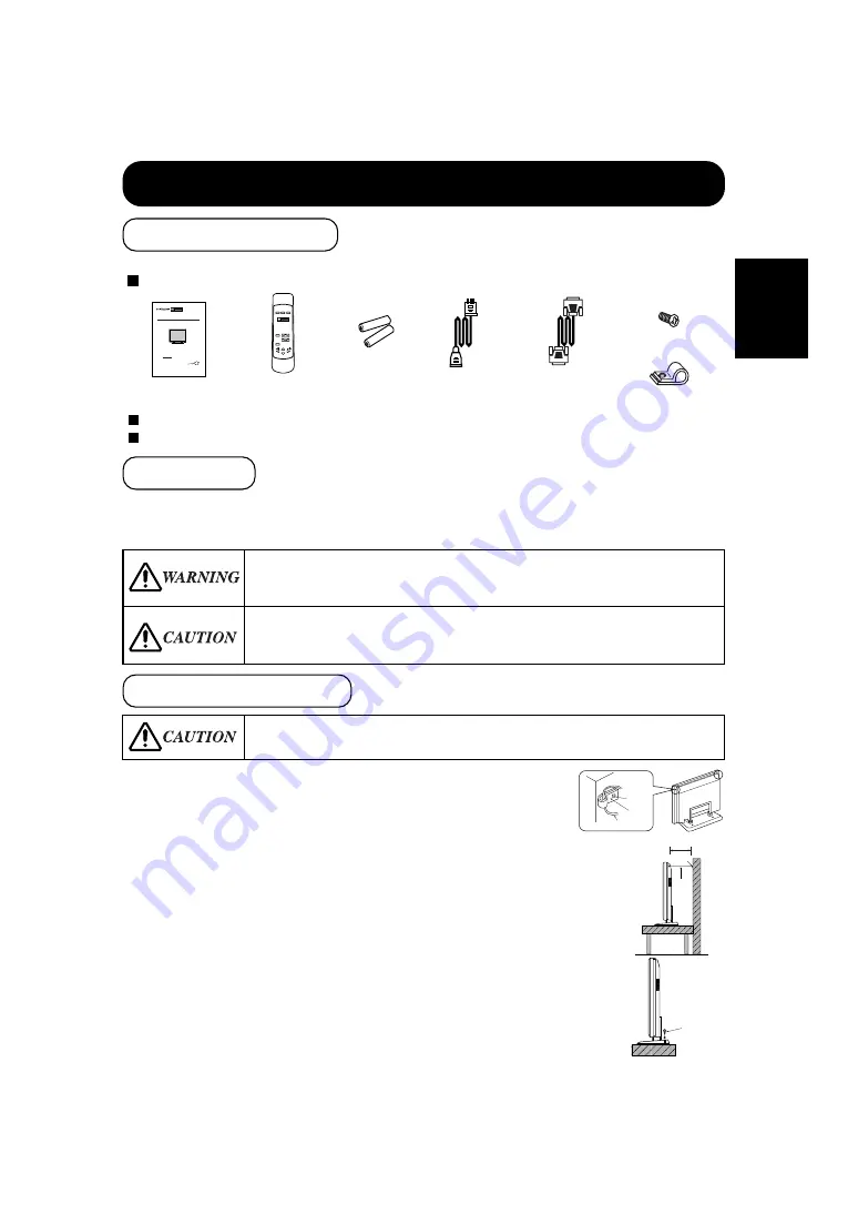
In order to prevent an internal temperature increase, maintain a space of 10cm or more between
the sides and other objects such as walls, etc., so that the ventilation holes are not blocked.

*

INSTALLATION INSTRUCTIONS

1) 

Using M4 screws (two), fasten the hooks included to the screw
holes at both ends of the top of the rear of the set as shown.

2) 

Using a commercially available cord, chain and clamp, secure the
set to a firm wall or post.

This product is complete with the display monitor, plus the accessories shown below.

If any of these accessories is missing, please contact your dealer.

Read the instruction manual (this book) and the warranty card carefully and keep them in a safe place for handy reference.

Retain the packing materials for use in future shipping or relocation.

Instruction manual

(this book)

Power cable

Signal cable, mini-

D-sub 15-pin

Remote-control

transmitter

Size AA

batteries x 2

Securing to a wall or post

Securing desktop

1) 

Using wood screws (two), fasten the set to the clamping screw
holes on the rear of the stand as shown.

2) 

Using commercially available wood screws, secure the set firmly
in position.

M4 screw x 2

Hook x 2

Screw

Hook

Cord or Chain

Cord

or

chain

Clamp

10cm or more

*

Two places

Wood screw

■ 

Have this unit mounted in a stable place. Take measures to prevent it from tumbling down to
avoid possible physical injury.

READ THE INSTRUCTIONS INSIDE CAREFULLY.
KEEP THIS USER MANUAL FOR FUTURE REFERENCE.

For future reference, record the serial number of your monitor.

SERIAL NO.

The serial number is located on the rear of the monitor.

This monitor is ENERGY STAR

®

compliant when used with a

computer equipped with VESA DPMS.
The ENERGY STAR

®

emblem does not represent EPA endorsement

of any product or service.
As an ENERGY STAR

®

Partner, Hitachi,Ltd. has determined that this product meets the ENERGY

STAR

®

guidelines for energy efficiency.

with

EasyMenu!

EasyMenu is HITACHI's On Screen Display function for easy operation.

USER MANUAL

MANUEL UTILISATEUR

Color Plasma Display Monitor

CMP307EU

Standard accessories

Installation

Anti-tumble measures

Summary of Contents for CMP307XU

Page 1: ...8 4 3 aspect ratio 160 degree viewing angle Theater operation capable of 16 million colors Multiscan capability PC Analog RGB Standard video inputs BNC s video Built in screen saver Internal speakers 37 HighResolutionXGA CMP307XU Display ...

Page 2: ...uilt in 3 9 x 1 2 speakers x 2 Main Power switch Sub Power button Adjustment buttons Input Changeover Adjustment Menu Selection Sound Volume Adjustment Contrast brightness color color tone sharpness Contrast brightness display size vertical position horizontal position clock frequencies clock phase Volume balance high low mute Infrared remote control unit provided VESA DPMS International ENERGY ST...

Page 3: ...nd ambient power lines the panel produces high quality display images free from color misconvergence and display distortion Multimedia input support The monitor comes complete with a mini D sub terminal and a BNC terminal for RGB input and with a composite S terminal and a component terminal for video input and even with stereo audio input terminals It allows hooking up with a number of devices fr...

Page 4: ...ume Adjustment 14 Contrast Adjustment 15 Sound Mute 15 Input Signal Status Display 15 On Screen Display System EasyMenu 16 OTHER FEATURES 22 Automatic Store 22 Reset Settings Initialization 23 Signal Check 23 Switching the Display Method 24 Power Save Mode 25 Sound Mode 25 TROUBLESHOOTING 26 Symptoms That Seemingly Appear to be Failures 26 Actions to Correct Abnormal Displays 27 PRODUCT SPECIFICAT...

Page 5: ... monitor if it fails If you find something unusual If smoke comes out If there is a strange smell If water enters the case If you drop the monitor or damage the cabinet 1 Turn off the monitor 2 Disconnect the power plug from the power point 3 Request for repair Warning and Caution are indicated in this guide and monitor itself Fire or electric shock may cause death or serious injury unless you fol...

Page 6: ...e monitor beside a window when snowing or raining or by a seaside are not recommended Do not damage or modify the power cord If you put something heavy on the power cord or pull squeeze heat the cord it may be damaged and it may cause fire or electric shock If the power cord is damaged call service center Fire or electric shock may cause death or serious injury unless you follow the instruction be...

Page 7: ...o not put things on the monitor Do not put things on the monitor or give some shock to the monitor The monitor may fall down or drop from a desk And it may cause injury 5 You may have serious injury or your property may be damaged unless you follow the instruction below Caution Do not bundle the power cord It will be heated up or it may cause a fire Caution for 200 240V operation only This equipme...

Page 8: ...or is fixed tightly when the signal cable is connected Also confirm the screws on the connector are tightened Plug the power cord of the monitor into a different socket from that for other equipment such as TV Radio etc Use a plug with ground terminal and make sure that it connects to the ground Precautions for TV Radio Keep the monitor away from TV or Radio Adjust TV or radio antennas in order fo...

Page 9: ...please contact your dealer Read the instruction manual this book and the warranty card carefully and keep them in a safe place for handy reference Retain the packing materials for use in future shipping or relocation Instruction manual this book Power cable Signal cable mini D sub 15 pin Remote control transmitter Size AA batteries x 2 Securing to a wall or post Securing desktop 1 Using wood screw...

Page 10: ...TANDBY RED ON GRN Front Cabinet front frame Stand 12 Panel Indicating lamp 13 Control panel RGB VIDEO VOLUME SELECT MENU VOLUME button 14 MENU button 16 RGB VIDEO button 14 SELECT button 16 The Adjustment button is located on the bottom Subpower button 13 Component Names ...

Page 11: ... MENU button 16 VOLUME button 14 SELECT button 15 External device connection terminals Rear RGB input terminals 10 S VIDEO VIDEO1 INPUT VIDEO VIDEO2 INPUT COMPONENT PR CR PB CB Y R L MONO AUDIO R L MONO AUDIO RGB INPUT RS232C IN R L MONO V H B G R AUDIO D SUB BNC RGB2 RGB1 Main power switch Power cable connector 10 13 VIDEO input terminals 11 ...

Page 12: ...and audio input terminals If the signal cable included does not match your PC consult your dealer after reading the section Signal Input 6 Insert one end of the power cable included into the rear panel power cable connector and the other end into a power socket If a power adapter is used ground the grounding wire to avoid electrical shocks and radio interference Complete grounding before connectin...

Page 13: ...ower switch is off The monitor is shipped with the power switch off 3 Make sure that the video equipment s power switch is off 4 Interconnect the signal input terminal on the monitor rear panel and the video equipment s signal output terminal to each other using an optional cable 5 Insert one end of the power cable included into the rear panel power cable connector and the other end into a power s...

Page 14: ...ller begins to lack responsiveness replace the batteries Strong light such as direct sunlight impinging on the photoreceptor of the remote control can cause operational failure Position this unit to avoid direct contact with such light Do not use batteries of any kind not recommended for this product Do not use new and old batteries together The batteries could explode or leak resulting in fires p...

Page 15: ...h to OFF For normal operations leave the main power switch set to ON and use the sub power button or the Power button of the remote control to turn the power on and off The indicating lamp lights when the power is turned on TIPS Avoid repeatedly turning the monitor on and off at short time intervals Failures might result from such operation Turn off the main power switch before leaving the monitor...

Page 16: ...ically While the on screen display system EasyMenu is not on display press the remote controller VOLUME button or or the unit VOLUME button or to adjust the sound volume VOLUME 30 VOLUME Set unit Remote controller VOLUME Press the RGB VIDEO button on the remote controller or the unit to switch the input in the sequence of RGB1 RGB2 VIDEO1 VIDEO2 RGB1 RGB1 D sub input RGB2 BNC input VIDEO1 composit...

Page 17: ...name Press the remote controller RECALL button to display the status of input signals on the screen Press the remote controller RECALL button once again to exit the screen display The contrast adjustment mode will exit when no keys are entered for 5 seconds The set itself does not have a RECALL button Input horizontal frequency Input vertical frequency 16 When you press these buttons the status of...

Page 18: ...PTIONS RETURN PICTURE MENU Pink Pink when brightness is selected Guidance Press the MENU button once again to exit the adjustment menu The adjustment menu will close automatically when no keys are entered for 10 seconds 17 21 Press the MENU button to open an adjustment menu allowing you to complete various adjustments and settings using the SELECT buttons remote controller and keys or the set SELE...

Page 19: ...SER COOL NORML WARM USER Set to the desired colors COLOR BALANCE R GAIN Red gain Red is weakened Red is strengthened Sets the color adjustment selected by the user with COLOR SELECT G GAIN Green gain Green is weakened Green is strengthened B GAIN Blue gain Blue is weakened Blue is strengthened OPTIONS PRESENTATION Presentation Sets to PUBLIC Sets to THEATER It can be selectd in 60 Hz vertical freq...

Page 20: ...es Sharpens display images Normally set to middle and towards for increased softness OPTIONS COLOR SELECT Color mode COOL NORMAL WARM COOL NORMAL WARM Set to the desired colors PRESENTATION Presentation Sets to PUBLIC Sets to THEATER Normally set to PUBLIC Set to THEATER to increase the number of colors even when the screen is dark GAMMA Gamma correction 1 0 2 2 2 8 1 0 2 2 2 8 Normally set to 2 2...

Page 21: ...k phase shifts slightly to right Adjust for clear character visibility DISPLAY INIT INITIALIZE Display initialization Set to Yes The Display menu adjustment values will be cleared and the Display menu will return Set to No The Display menu will return the adjustment values will not be cleared Clear the user signal preset data DISPLAY in VIDEO is selected DISPLAY SIZE Display size NORMAL WIDE SQ N ...

Page 22: ...o see characters or images crisp or to LINEAR to view them smooth F U N C T I O N V I D E O 1 LINE INTP Line correction Set to OFF Set to ON Set to ON when playing a 3D video disc Set to OFF in most cases 3D COMB Three dimensional Y C separation Set to OFF Set to ON Set to OFF if video images appear unnatural Set to ON in most cases VIDEO SYSTEM Video system AREA1 AREA2 NTSC PAL SECAM 4 NTSC M PAL...

Page 23: ...s to ON The image will move automatically to reduce burn in The amount of movement is set with Moving Dots and the move time is set with Moving Timer 1 60 min Use zero 0 to check the movement range The movement time would be approximately 1 sec MOVING DOTS Amount of screen movement selection Reduces the amount of movement Increases the amount of movement MOVING TIMER Movement time interval selecti...

Page 24: ...und volume Sound balance Treble Bass Mute volume Input status automatic display Half tone Enlargement Line correction Three dimensional Y C separation HD signal Input select One set can be recorded During normal signal reception Brightness Contrast Gamma correction Input signal level Display area One set can be recorded during common RGB1 RGB2 input one set of two can be recorded during normal sig...

Page 25: ... the display darkens and display continues until the correct signal is received Eithe VIDEO1 or VIDEO2 is displayed on VIDEO input The Easy Menu shown to the right will be displayed when the SELECT button is used to select DISPLAY and moreover DISPLAY INT is selected from the On screen Display System Easy Menu during RGB1 RGB2 input If the key select Yes of the SELECT button is pressed at this tim...

Page 26: ...e remote control are pressed Refer to Display Area Display may not be correct in some cases depending on the signal conditions Switching when the RGB input jack is selected Switching when the Video Input jack is selected Problem This setting is used normally When it is desired to slightly enlarge images when black stripes appear at the top and bottom of the screen When it is desired to view a Sque...

Page 27: ...asy Menu shown to the right appears on the screen when the sound mode is selected After approximately 5 sec the brightness of the Easy Menu lowers and display continues until the sound mode is canceled In sound mode sound volume can be adjusted SOUND MODE 25 25 MENU Remote controller POWER SAVE MENU Remote controller When the RGB input jack is selected This unit meets the power saving requirements...

Page 28: ...gher contrast and brightness Check the way the signal cable is connected The display image appears flowing slantwise Text displayed across the screen appears vertically streaked with the characters in vertical columns blurred Adjust the dot clock frequency and phase Adjust the dot clock frequency first the dot clock phase next Text displayed across the screen appears blurred A fine pattern flicker...

Page 29: ...pears blurred across the screen make the adjustment instructed in Symptom 2 Press or to make the text appear without flickering Symptom 2 Text displayed across the screen appears blurred in its entirety display 3 A fine pattern flickers when displayed on the screen display 4 Example Display 3 Display 4 Adjustment procedure Press MENU button to open the adjustment menu Press the key of the SELECT b...

Page 30: ...A 2 2A Power consumption 390W Mass 884 W x 684 H x 99 7 D mm excluding the stand 884 W x 766 H x 300 D mm including the stand Ambient conditions VIDEO1 video input terminal Composite video RCA pin x 1 VIDEO1 S video input terminal S VIDEO S terminal x 1 VIDEO1 audio input terminal RCA pin L R x 1 VIDEO2 video input terminal Composite video RCA pin x 3 Y PB PR CB CR VIDEO2 audio input terminal RCA ...

Page 31: ...t unit Ceiling mount unit Type CMPAK04 Angle change type 0 20 Adjustment five steps is possible External dimensions 675 W x 560 H x 77 D mm Type CMPAT04 Angle change type 0 25 Adjustment five steps is possible External dimensions 480 W x 959 H x 330 D mm To preserve the performance of this product and to maintain safety always use one of the special mount units for installation Special mount units...

Page 32: ...mmended mode 10 1024 X 768 70 07 56 48 75 00 XGA 11 1024 X 768 75 03 60 02 78 75 XGA 12 1280 X 1024 60 02 63 98 108 00 SXGA compressed partial 13 Apple 640 X 480 66 67 35 00 30 24 14 832 X 624 74 55 49 73 57 28 15 1024 X 768 74 93 60 24 80 00 The type of video board or connecting cable used may not allow for correct displays Set H POSITION V POSITION CLOCK and PHASE When a signal has been input wi...

Reviews: