background image


23


EN

GLISH


Adjusting the Contrast Setting 

To adjust Contrast setting you should follow the steps below: 
1.  Bring-up the OSD “

Main Menu

”. 

2. Use ‘

Select

’ button to move forward to the contrast icon and highlight it. 

3. Use ‘

Right

’ and ‘

Left

’ button to adjust its value. The range for adjustment is from 0 to 

100. ‘

Right

’ button will increase the Contrast setting and ‘

Left

’ will decrease it. 

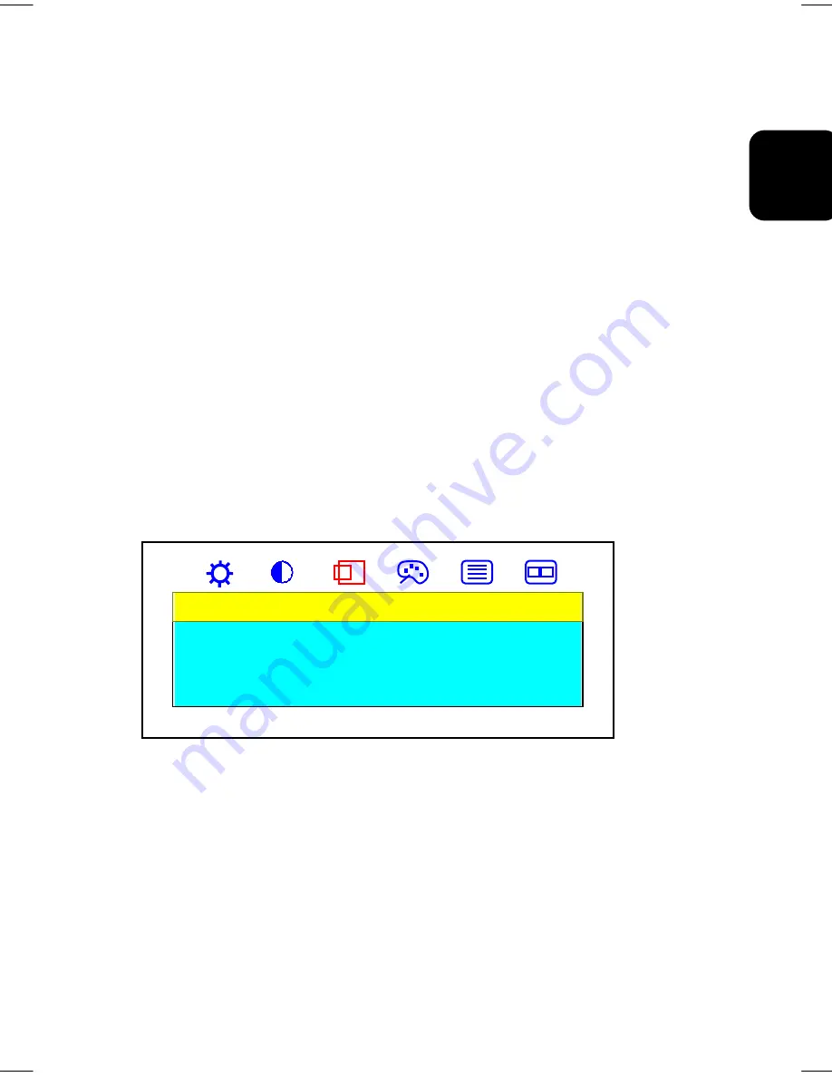
Adjustment in the “Display” submenu 
To adjust Display settings you should follow the steps below: 
1.  Bring-up the OSD “

Main Menu

”.  

2. Use ‘

Select

’ button to move forward to ‘Display’ icon and highlight it. This will bring-up 

the “

Display

” submenu. There are three items for your choice in this submenu: Exit, H. 

Position and V. Position. 

3. Use ‘

Right

’ and ‘

Left

’ keys to choose the item you need and then press ‘

Select

’ to 

highlight and select it. 
If ‘Exit’ is selected, it will exit the “

Display

” submenu and forward to the next item in the 

Main Menu

”. (i.e., Color icon.) 

If ‘H. Position’ is selected, then you can adjust it by ‘

Right

’ and ‘

Left

’ buttons. ‘

Right

’ 

button will move the image to the right and ‘

Left

’ button will move the image to the left. 

If ‘V. Position’ is selected, then you can adjust it by ‘

Right

’ and ‘

Left

’ buttons. ‘

Right

’ 

button will move the image upward and ‘

Left

’ button will move the image downward. 


Display 

Exit 

H. Position 

V. Position


Adjustment in the “Color” submenu 
To adjust Color settings you should follows the steps below: 
1.  Bring-up the OSD “

Main Menu

”. 

2. Use ‘

Select

’ button to move forward to ‘Color’ icon and highlight it. This will bring-up 

the “

Color

” submenu. There are five items for your choice in this submenu: Exit, Color 

Temp, Luminance, Hue, and Color. 

3. Use ‘

Right

’ and ‘

Left

’ buttons to choose the item you need and then press ‘

Select

’ to 

highlight and select it. 

Summary of Contents for CML200UXWB

Page 1: ...ated on the rear of the monitor This monitor is ENERGY STAR compliant when used with a computer equipped with VESA DPMS The ENERGY STAR emblem does not represent EPA endorsement of any product or service As an ENERGY STAR Partner Hitachi Ltd has determined that this product meets the ENERGY STAR guidelines for energy efficiency USER MANUAL MANUEL D UTILISATION BEDIENUNGSANLEITUNG MANUAL DE USUARIO...

Page 2: ...cludes decreased image clarity or reduced brightness due to natural aging of the monitor display In addition this warranty does not cover phosphor burn Phosphor burn can occur when a monitor is left with one static image for extended periods of time during which the image may become burned into the phosphors This limited warranty does not cover damage occurring in shipping or in storage after you ...

Page 3: ...IMITATION OR EXCLUSION MAY NOT APPLY TO YOU THIS WARRANTY GIVES YOU SPECIFIC LEGAL RIGHTS AND YOU MAY HAVE OTHER RIGHTS WHICH VARY STATE TO STATE THIS WARRANTY APPLIES TO NEW CURRENT PRODUCTS ONLY AND DOES NOT APPLY TO PRODUCTS SOLD AFTER THEY ARE DISCONTINUED OR REFURBISHED For Canadian Customers only Warranty Policy Hitachi Industrial Products are guaranteed to be free from defects in workmanshi...

Page 4: ...r warranties guarantees or agreements whether expressed or implied and no person dealer or Company is authorized to change modify or extend its terms in any manner whatsoever Hitachi Canada Inc shall not be responsible for any damages or loss of any kind attributed to the product rendered defective during usage or attributed to incompatibility problems of any linked equipment including software NE...

Page 5: ...press written authority TRADEMARK ACKNOWLEDGEMENT VGA is a registered trademark of International Business Machines Corporation VESA is a trademark of a nonprofit organisation Video Electronics Standard Association ENERGY STAR is a trademark of Environmental Protection Agency EPA CONTENTS Introduction 6 Features 6 Using This Display Safely 7 Warning 8 Caution 11 FCC Statement Warning 13 For the Cus...

Page 6: ... Adjusting Your Display 21 Summary of Control Buttons 21 Displaying the OSD Main Menu 21 Selecting Items in the OSD Menu 22 Doing Adjustment in the OSD Menu 22 Using the Direct Keys 27 KeyLock Function 28 Troubleshooting 30 Technical Information 31 Display Information 31 Video Modes 32 Unknown Video Modes 33 ...

Page 7: ...reen display for monitor settings adjustment and configuration with ease and instant feedback Support analog and digital video input for direct and immediate replacement of CRT displays Build in speakers microphone and earphone jack A tilt feature to optimize viewing position An anti glare coating on the panel to reduce the reflection of ambient light Flicker free performance across all recommende...

Page 8: ...uct Notice example 1 Shock Caution This Ì symbol indicates that caution should be taken and within the triangle Ì is a picture depicting Shock caution Notice Example 2 Disassembly Prohibited In the barred circle is an action that must not be done and the picture in this one depicts Disassembly Prohibited Notice Example 3 Unplug power Cord from Socket In the symbol is an action that should be taken...

Page 9: ... This will cause the internal temperature to rise and result in fire or malfunction Do place on racks that fix the display in leaning position This will change the flow of air through the air vents and cause the internal temperature to rise resulting in fire or malfunction Placing Objects in Device DO NOT put paper clips pins metallic objects or combustible items in the ventilation holes Using the...

Page 10: ...olonged periods unplug the power cord Leaving it plugged in may result in fire When unplugging or plugging in the power cord insure that your hands are dry Handling with wet hands may result in electrical shock Poor Electrical Contact in Electric Plug etc The following must be done to prevent bad contact in the electrical plug that may result in fire Insure that electric plug is inserted in fully ...

Page 11: ...emperature may cause condensation on the outside and internally Using the device in this condition may result in fire or electrical shock Leave the device at the location for a few hours before using Aluminium Electrolysis Condenser The electrolyte condenser used in the AC adapter has a limited life If used past the life span approximately 5 years replace the AC adapter Leakage or drying up of the...

Page 12: ...ng may break and cause damage to the devices that are connected Stand When adjusting the angle hold the top left and right edges with both hands and move slowly Using only one hand may cause it to fall DO NOT place your hand near the stand when adjusting the LCD forward or back Your fingers may get caught and cause injury Eyestrain When continuously looking at the display while working keep the wo...

Page 13: ...televisions noise may enter their sound reception If this should happen try the following Place in a location as far away from radios and televisions as possible Change the facing of the antenna on the radio or television Use a different electrical socket Storing the Plastic Bag Keep the plastic bag used to wrap the display away from young children The bag may cause suffocation ...

Page 14: ... on the user is encouraged to try to correct the interference by one or more of the following measures Reorient or relocate the receiving antenna Increase the separation between the equipment and receiver Connect the equipment into an outlet on a circuit different from that to which the receiver is connected Consult the dealer or an experienced radio TV technician for help INSTRUCTIONS TO USERS Th...

Page 15: ...n obtain an appropriate safety approved extension lead or consult your dealer Should it be necessary to change the mains plugs this must be carried out by a competent person preferably a qualified electrician If there is no alternative to cutting off the mains plug ensure that you dispose of it immediately having first removed the fuse to avoid a possible shock hazard by inadvertent connection to ...

Page 16: ...e following items The LCD monitor AC power adapter with attached power cable A power cord Analog video signal cable Digital video signal cable Audio mic cable Speaker audio cable Speaker housing The User s Manual Note Place the display on a flat sturdy surface Choose an area free from excessive heat moisture and sunlight Locations and Functions of Controls There are three control buttons and one p...

Page 17: ...nnect the power and video signal cables 1 Locate the AC power adapter with attached power cable 2 Connect the power cable to the power jack on the back of the display DC IN as shown below 3 Plug the three prong power cord into a power outlet and plug the other end into the AC power adapter 4 Plug the speaker audio cable black into AUDIO OUT port and then plug the red side into right speaker box th...

Page 18: ...17 ENGLISH Note For best display performance it is strongly recommended that you use Auto Setup to automatically configure your display s settings only for Analog input Speaker housing ...

Page 19: ...e power consumption to low levels when your PC goes into its power saving mode See Minimizing Power Consumption on page 20 for more information If your PC doesn t use industry standard power save signaling techniques you can reduce power consumption by turning off the display when it won t be used for an extended period You can turn the display off even if you leave your PC in running Note Because...

Page 20: ...200 If you use a lower resolution such as 640 x 480 the image is expanded to fill the screen Your display supports many common video modes as shown in Video Modes on page 31 Check the documentation supplied with your PC and video adapter card to find out which modes they support To see what the video mode in your Microsoft Windows please check Windows settings in your PC Setting the Refresh Rate T...

Page 21: ...play accepts the signals for the three standard power saving modes Standby Suspend and Sleep For any of these conditions the display will go into Sleep mode Caring for and Cleaning the Display To maximize screen life and prevent damage to the LCD panel we recommend that you Use the display power management system if available on your PC If you don t use a power management system turn off the displ...

Page 22: ...te Hold down this key for 2 seconds will clear OSD menu Right Move upward through the choice in the OSD submenu If an adjustment bar is displayed this button increases the setting value Note This key is also used as direct key to bring up OSD Audio Video Left Move downward through the choice in the OSD submenu If an adjustment bar is displayed this button decreases the setting value Note This key ...

Page 23: ...re you can select to display mode information Mode Info select OSD Display select scale center choose language you preferred select input signal Source and recall factory settings for further adjustment See Doing Adjustment in the OSD Menu on page 22 Selecting Items in the OSD Menu To select items in the OSD Main Menu you will use the Select button on the front panel of the display To select items...

Page 24: ...then press Select to highlight and select it If Exit is selected it will exit the Display submenu and forward to the next item in the Main Menu i e Color icon If H Position is selected then you can adjust it by Right and Left buttons Right button will move the image to the right and Left button will move the image to the left If V Position is selected then you can adjust it by Right and Left butto...

Page 25: ...m 0 to 100 Right button will increase the RGB setting and Left will decrease it It will adjust the saturation of the color If Black Level Adjust is selected use Right and Left button to adjust its value The range for adjustment is from 0 to 100 Right button will increase the RGB black level setting and Left will decrease it It will adjust the black level of the color Adjustment in the Clock Phase ...

Page 26: ...e 27 for more detail information If Clock is selected then you can adjust it by Right and Left buttons Right button will increase the number of pixels per line and Left button will decrease the number of pixels per line Note We recommend you do Auto Setup first And adjusting the clock setting only if the image looks incorrect If Phase is selected then you can adjust it by Right and Left buttons No...

Page 27: ...rmation displayed in it If OSD Display is selected it will bring up OSD Display submenu Use Right and Left buttons to highlight and Select key to select H or V Position This will show up the corresponding bar on menu and you can adjust its setting by Right and Left buttons Right button will move the OSD menu to the right or upward and Left button will move the OSD menu to the left or downward If S...

Page 28: ...OSD Auto Setup and Audio submenu Auto Setup by Direct Key Use Auto Setup whenever you apply a new video mode or change the refresh rate While the Auto Setup routine is running you should have a stable image displayed on the screen Do not move items around the screen play games or view video during Auto Setup Once you have executed Auto Setup for a particular mode the display will store the new val...

Page 29: ...he item you need and then press Select to highlight and select it Audio Exit Source Audio Mute Volume Surround If Exit is selected it will exit and close the OSD If Source is selected it will bring up Source submenu The description refer to page 26 If Audio Mute is selected it will bring up Audio Mute submenu with Yes and No prompt for your confirmation Use Right and Left buttons to choose and Sel...

Page 30: ...io surround output or not Key Lock Functions Press RIGHT and SELECT keys and power on the monitor will cause Key Lock function for keypad locked But this function did not have effect on the power button The Key Lock message is shown as below Keypad Locked Key Unlock Function Press RIGHT and SELECT keys and power on the monitor again when keypad locked will cause Key Unlock function for keypad unlo...

Page 31: ...tween the display and the computer The cable connectors must be pushed in all the way B The message Check Cable appears on my display This message appears when the video cable is not properly connected to the computer 1 Make sure the analog video cable is plugged into the Analog Video Input port on the back of the display 2 Make sure the other end of analog video cable is plugged into the PC s vid...

Page 32: ...llions Power Input 100 240 VAC Full Range 50 60 Hz 1 2 A 110V 0 6 A 230V Maximum power consumption 70W Signal Input Video Signal Sync signals Analog RGB positive 0 7VPP 75Ω Separate TTL Level Digital TMDS 0 3Vp p differential Line horizontal frequency Analog 31 5 kHz 80 kHz Digital 31 5 kHz 75 kHz Raster vertical frequency Analog 56 Hz 75 Hz Digital 60 Hz Pixel dot clock 162 MHz maximum Recommende...

Page 33: ...tes Other combinations are possible but may require adjustments to the image For optimum performance set your PC to a screen resolution of 1600 x 1200 at a 60 Hz refresh rate Analog Supported Resolution dots x lines Vertical Frequency Refresh Rate VGA 640 x 480 640 x 480 640 x 480 60 Hz 72 Hz 75 Hz SVGA 800 x 600 800 x 600 800 x 600 800 x 600 56Hz 60 Hz 72 Hz 75 Hz XGA 1024 x 768 1024 x 768 1024 x...

Page 34: ...designed to work with standard video modes However not all video graphic cards use only standard display modes Your LCD monitor uses state of the art technology which is designed to synchronize to any display mode We recommend choosing one of the supported modes listed above If you choose an unknown mode you will need to manually adjust the clock phase and image position If you must use an unknown...

Page 35: ... ITALY Tel 39 02 487861 Tel 39 02 38073415 Servizio Clienti Fax 39 02 48786381 2 Email customerservice italy hitachi eu com HITACHI Europe AB Box 77 S 164 94 Kista SWEDEN Tel 46 0 8 562 711 00 Fax 46 0 8 562 711 13 Email csgswe hitachi eu com HITACHI EUROPE S A S Lyon Office B P 45 69671 BRON CEDEX FRANCE Tel 04 72 14 29 70 Fax 04 72 14 29 99 Email france consommateur hitachi eu com HITACHI EUROPE...

Reviews: