HITACHI CML155XW LCD Monitor Service Manual (v1.0)
11
4)
PCB Assembly Removal:
Caution:
When serving or replacing the panel, disconnect the DC power jack completely.
(a)
Unplug all connected wires from the PCB.
(b)
Remove 3 screws indicated as “C” from the inverter board, and then remove the board
carefully. (left side in Fig. 4-3)
(c)
Remove 3 screws indicated as “D” from the audio board, and then remove the board
carefully.
(d)
Remove 7 screws indicated as “E” from the main board connected with front cover. (Fig.
4-3)
5)
Panel Removal:
(a)
Remove 6 screws indicated as “F” from the front cover (Fig. 4-3) to remove the panel.
C
Fig. 4-3
D
F
E
Summary of Contents for CML155XW
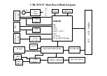
Page 21: ...Appendix A CML155XW Main Board Block Diagram ...
Page 23: ...Appendix B CML155XW Main Board Circuits ...
Page 24: ......
Page 25: ......
Page 26: ......
Page 27: ......
Page 28: ......
Page 29: ......
Page 30: ...Appendix C CML155XW Audio Board Circuit ...
Page 31: ......
Page 32: ...Appendix D CML155XW Key Board Circuit ...
Page 33: ......
Page 34: ...Appendix E CML155XW Inverter Board Circuit ...
Page 35: ......
Page 36: ...Appendix F CML155XW Troubleshooting Flow Charts ...
Page 39: ...Appendix G CML155XW Repair Parts List ...
Page 40: ...THE UPDATED PARTS LIST FOR THIS MODEL IS AVAILABLE ON ESTA ...
Page 41: ...Appendix H CML155XW Mechanical Disassembly ...
Page 42: ......
Page 43: ...Appendix I CML155XW Printed Circuit Boards ...
Page 44: ......
Page 45: ......
Page 46: ......
Page 47: ......


