


3
4
9. W
iring diagram
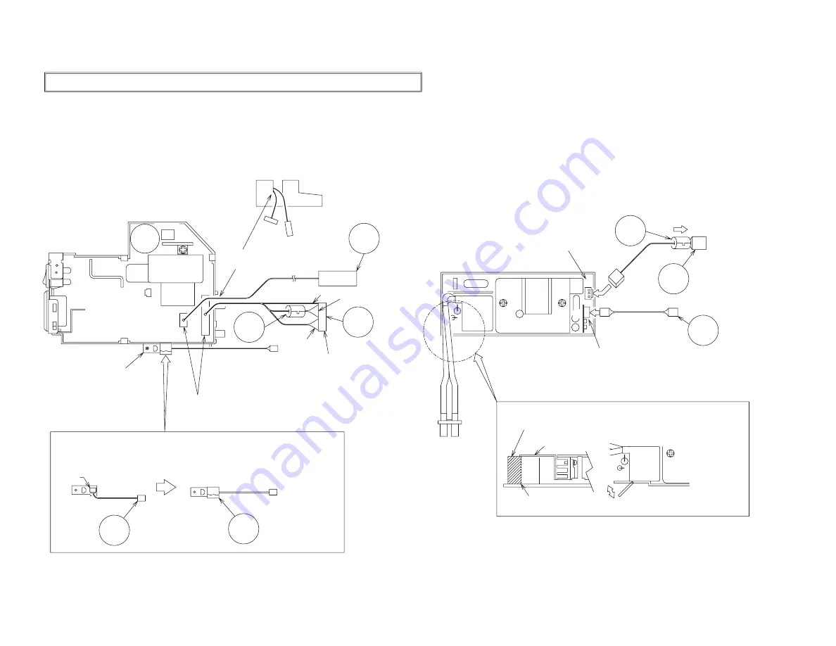
Wiring for Circuit Power Supply and Ballast Power Supply Boards
Wiring for Ballast Power Supply Board
(1) Keep a record of the ballast power supply lot number in the 100% inspection record.
(2) Cut off the PVC sheet.
(3) Connect the CNPWR.
(4) Install the FEB2.
(5) Connect the CNBAR.
(6) Install the ballast shield (in accordance with the general assembly drawing).
Wiring for Circuit Power Supply Board
(1) Keep a record of the circuit power supply lot number in the 100% inspection record.
(2) Connect the TSW.
(3) Install the FEB3.
(4) Connect the CNPOW.
(5) Connect the CNTH.
(6) Apply the TAP3.
Pass the leads through the
board holder notch.
Connect the CNBAR to connector J2,
while holding down the small board mounted
with the J2 (to prevent stress on the small board).
Cut off the PVC sheet by bending it back and forth 2 or 3 times with
your hand, while holding down the double-coated adhesive tape affixed
to the igniter transformer so the tape cannot come off.
Perforation
Igniter transformer
Cut off the sheet by bending it back
and forth 2 or 3 times.
Connect the FEB2 (ferrite core) to the
CNPWR then move the CNPWR to
the connector as illustrated below:
Install the sensor board after completing the following steps:
Connect the CNTH to connector
E950 on the sensor board.
Make sure that connector E950 has
been securely connected then apply
the TAP3 (to prevent detachment).
Connect the CNPWR to connector
J1 then make sure that the CNPWR
is completely locked.
Connect the FEB3 (ferrite core)
to pins 2-8 of the CNPOW.
Make sure that the CN102 and the CN104 have been securely
connected (since they cannot be checked in subsequent processes).
CN104
CN102
CN101
1pin
2-8pin
9-14pin
FEB3
CNPOW
TSW
Sensor board
Sensor board
CNTH
E950
TAP3
J1
J2
CNBAR
FEB2
CNPWR
Summary of Contents for C3S3
Page 34: ...33 Connector connection diagram C3S3E C3XM3E ...
Page 42: ...41 6 5 4 3 2 1 6 5 4 3 2 1 A B C D E F G POWER UNIT BALLAST C3S3 C3XM3 ...
Page 43: ...42 6 5 4 3 2 1 6 5 4 3 2 1 A B C D E F G POWER UNIT CIRCUIT C3S3 C3XM3 ...
Page 44: ...A B C D E F G 5 4 3 2 1 6 6 5 4 3 2 1 PWB assembly DRIVE 1 C3S3 C3XM3 43 1 ...
Page 45: ...A B C D E F G 5 4 3 2 1 6 6 5 4 3 2 1 PWB assembly DRIVE 2 C3S3 C3XM3 44 ...
Page 46: ...A B C D E F G 5 4 3 2 1 6 6 5 4 3 2 1 PWB assembly DRIVE 3 C3S3 C3XM3 45 ...
Page 47: ...A B C D E F G 5 4 3 2 1 6 6 5 4 3 2 1 PWB assembly DRIVE 4 C3S3 C3XM3 46 ...
Page 48: ...A B C D E F G 5 4 3 2 1 6 6 5 4 3 2 1 PWB assembly DRIVE 5 C3S3 C3XM3 47 ...
Page 49: ...A B C D E F G 5 4 3 2 1 6 6 5 4 3 2 1 PWB assembly DRIVE 6 C3S3 C3XM3 48 ...
Page 50: ...A B C D E F G 5 4 3 2 1 6 6 5 4 3 2 1 PWB assembly DRIVE 7 C3S3 C3XM3 49 ...
Page 51: ...A B C D E F G 5 4 3 2 1 6 6 5 4 3 2 1 PWB assembly DRIVE 8 C3S3 C3XM3 50 ...
Page 52: ...A B C D E F G 5 4 3 2 1 6 6 5 4 3 2 1 PWB assembly DRIVE 9 C3S3 C3XM3 51 ...
Page 53: ...A B C D E F G 5 4 3 2 1 6 6 5 4 3 2 1 PWB assembly DRIVE 10 C3S3 C3XM3 52 ...
Page 54: ...A B C D E F G 5 4 3 2 1 6 6 5 4 3 2 1 PWB assembly SIGNAL 1 C3S3 C3XM3 53 ...
Page 55: ...A B C D E F G 5 4 3 2 1 6 6 5 4 3 2 1 PWB assembly SIGNAL 2 C3S3 C3XM3 54 ...
Page 56: ...A B C D E F G 5 4 3 2 1 6 6 5 4 3 2 1 PWB assembly SIGNAL 3 C3S3 C3XM3 55 ...
Page 57: ...A B C D E F G 5 4 3 2 1 6 6 5 4 3 2 1 PWB assembly INPUT 1 C3S3E C3XM3E 56 ...
Page 58: ...A B C D E F G 5 4 3 2 1 6 6 5 4 3 2 1 PWB assembly INPUT 2 C3S3E C3XM3E 57 ...
Page 59: ...A B C D E F G 5 4 3 2 1 6 6 5 4 3 2 1 PWB assembly INPUT 3 C3S3E C3XM3E 58 ...
Page 62: ...THE UPDATED PARTS LIST FOR THIS MODEL IS AVAILABLE ON ESTA ...
Page 64: ...63 ...