


--- 13 ---
9-1-2. Reassembly
Reassembly can be accomplished by following the disassembly procedures in reverse. However, particular
attention should be given to the followng items.
(1) Tightening torque
Seal Lock Flat Hd. Screw M4 x 10 [15] ........................................ 14 to 22 kgf•cm (12 to 19 in•lbf)
Bolt (W/Flange) M8 x 15.5 [19] .................................................... 80 to 120 kgf•cm (70 to 105 in•lbf)
Seal Lock Flat Hd. Screw M5 x 14 [21] ........................................ 28 to 42 kgf•cm (24 to 37 in•lbf)
Machine Screw M4 x 8 [23] .......................................................... 15 to 25 kgf•cm (13 to 22 in•lbf)
Machine Screw (W/Washers) M5 x 45 (Black) [27] ...................... 28 to 42 kgf•cm (24 to 37 in•lbf)
Tapping Screw D4 x 10 [32] ......................................................... 15 to 25 kgf•cm (13 to 22 in•lbf)
Tapping Screw (W/Flange) D4 x 20 (Black) [46] .......................... 15 to 25 kgf•cm (13 to 22 in•lbf)
Brush Cap [50] ............................................................................. 5 to 15 kgf•cm (4.5 to 13 in•lbf)
Hex. Hd. Tapping Screw D4 x 60 [54] .......................................... 15 to 25 kgf•cm (13 to 22 in•lbf)
Clamp Nut [72] ............................................................................. 15 to 25 kgf•cm (13 to 22 in•lbf)
Machine Screw M3.5 x 8.5 of the Switch [30] .............................. 4.5 to 7.5 kgf•cm (4 to 6.5 in•lbf)
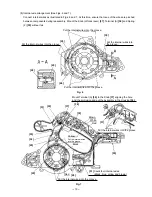
(2) Reassembly of the Armature Ass'y DC 24V [44]
Prior to assembling the Armature Ass'y DC 24V [44], ensure that the Rubber Ring [2] is properly inserted into
the groove of the bearing case within the Gear Cover Ass'y [3]. At this time, be careful not to damage the
Rubber Ring [2].
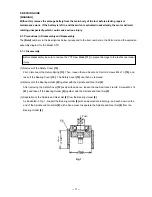
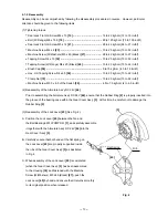
(3) Reassembly of the Lock Lever [45] (See Fig. 4.)
A. Position the Lock Lever [45] between the fan and
the Ball Bearing 6201VVCMPS2L [1], and carefully assemble
it together with the Armature Ass'y DC 24V [44] into the
Gear Cover Ass'y [3].
B. Carefully ensure that both ends of the flat spring on
the Lock Lever [45] are properly supported inside
the ribs of the Gear Cover Ass'y [3] as illustrated
in Fig. 4.
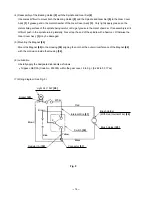
C. When assembly of the Lock Lever [45] is completed
(when the Gear Cover Ass'y [3] has been assembled
to the Housing [34] and fastened with the Machine
Screw (W/Washers) M5 x 45 (Black) [27]), push the
Lock Lever [45] by hand and ensure that it returns smoothly
to its original position when released.
Fig. 4
[45]
[3]
Flat Spring
Rib
Summary of Contents for C 7D
Page 25: ......


