Introduction
1–27
Hitachi AMS 2000 Family Storage System Service Guide
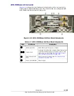
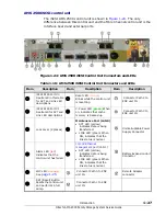
AMS 2500 iSCSI control unit
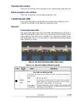
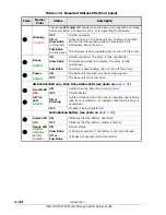
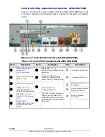
The iSCSI AMS 2500 control unit is shown in
. The only
difference between this control unit and the Fibre Channel control unit is the
interface board and external ports.
•
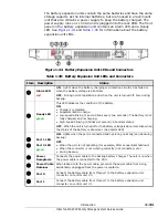
Figure 1-24: AMS 2500 iSCSI Control Unit Connectors and LEDs
•
•
Table 1-16: AMS 2500 iSCSI Control Unit Connectors and LEDs
Item
Description
Item
Description
Item
Description
1
iSCSI RJ45 Port #0
See item 9 in this table
for ACT and Link LED
descriptions
7
Reset LED
(orange)
Blinks while the control unit
is resetting
Connector Path 2 to
ENC unit IN
2
iSCSI RJ45 Port #1
See item 9 for ACT and
Link LED descriptions
8
C- Power LED
(green)
When
on, indicates that cache
memory is backed up.
Connector Path 3 to
ENC unit IN
3
Lock Lever (2 places)
9
Maintenance Port (LAN 0)
• ACT LED (yellow)
indicates data is being
transferred.
• LINK LED (green) When
ON, indicates that the
link status is normal.
Uninterruptable Power
Supply Connector
4
Alarm LED
(red)
Indicates that the
control unit has failed.
10/100 Ethernet
management port
(LAN 1)
• ACT LED (yellow)
indicates data is being
transferred.
• LINK LED (green) When
ON, indicates that the
link status is normal.
Battery Expansion Unit
Connector
5
LOC LED
(orange)
See
Connector Path 0 to ENC
unit IN
Remote Adapter
connector
6
RST (Reset) Button
Resets the control unit
and performs a full
dump.
Connector Path 1 to ENC
unit IN
Summary of Contents for AMS 2100
Page 8: ...viii Contents Hitachi AMS 2000 Family Storage System Service Guide ...
Page 98: ...3 6 Replaceable parts Hitachi AMS 2000 Family Storage System Service Guide ...
Page 158: ...5 10 Maintenance Hitachi AMS 2000 Family Storage System Service Guide ...
Page 182: ...7 8 Errors Hitachi AMS 2000 Family Storage System Service Guide ...
Page 191: ...Hitachi AMS 2000 Family Storage System Service Guide ...

