36
II. FEATURES AND FUNCTIONS
4.1 VIDEO SETTING
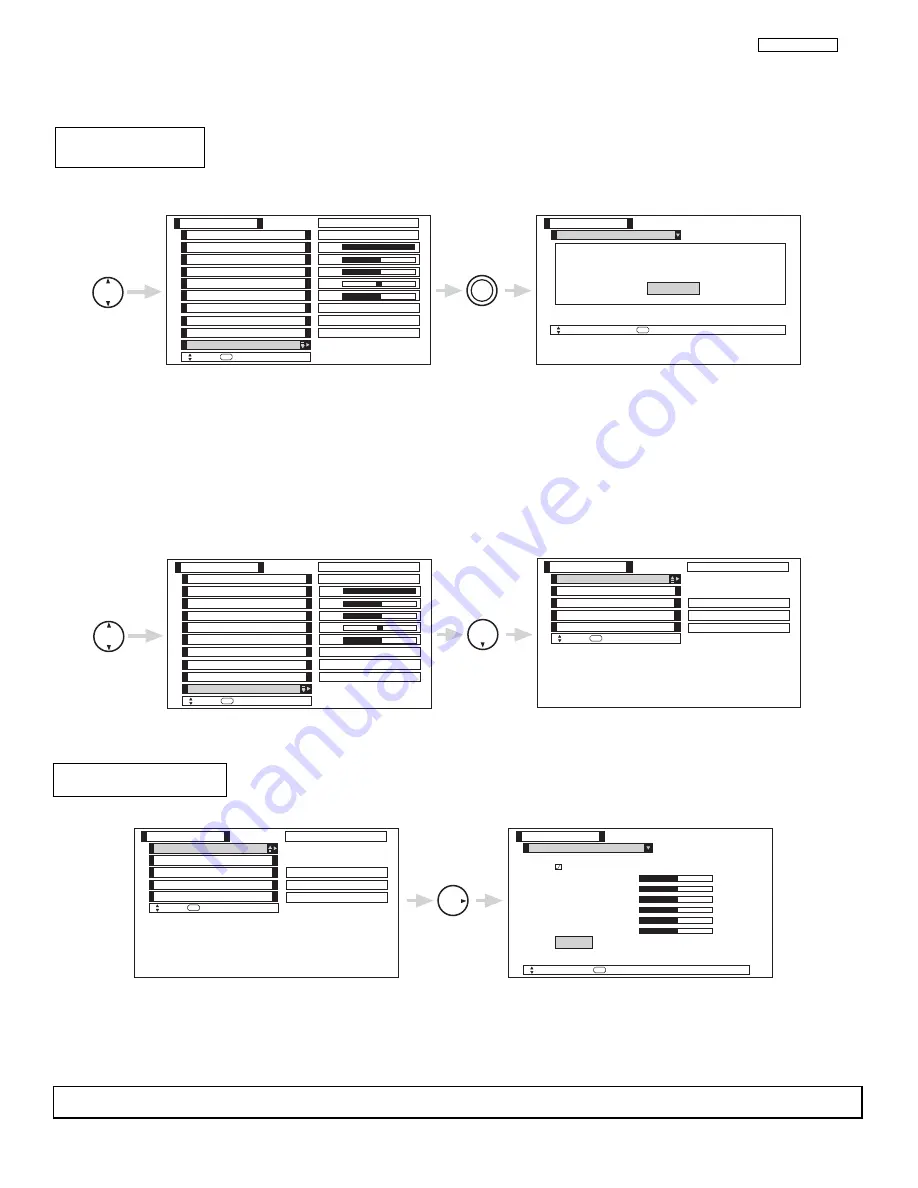
This function allows you to Reset the Video Menu Settings of the present input and return it to the Day or Night
conditions depending on the selected Video mode.
Use THUMB STICK to highlight functions.
Press down on THUMB STICK to select Reset Video Settings.
Use THUMBSTICK
to access other video settings.
You can customize each of the Video Inputs to your preference to increase viewing performance and pleasure, depending upon the
video program being viewed. If Reset is selected, only the selected mode will reset to the initial conditions as explained above.
If Reset is selected in Video:1 mode, only Video:1 mode will return to factory conditions.
Reset Video
Settings
THUMB
STICK
SELECT
THUMB
STICK
SELECT
Color
Brightness
Contrast
Picture Mode
Video
Move
SEL
Select
Color Temperature
Sharpness
Tint
Contrast Mode
Black Enhancement
100%
50%
50%
50%
High
Day
Night
Reset Video Settings
ANT A/B
High
Dynamic
Picture Mode
Video
Move
SEL
Select
S e l e c t “ R e s e t ” t o R e t u r n t h e V i d e o
m e n u S e t t i n g s o n t h i s i n p u t t o t h e
o r i g i n a l f a c t o r y s e t t i n g s .
R e s e t
THUMB
STICK
SELECT
THUMB
STICK
Color
Brightness
Contrast
Picture Mode
Video
Move
SEL
Select
Color Temperature
Sharpness
Tint
Contrast Mode
Black Enhancement
100%
50%
50%
50%
High
Day
Night
Reset Video Settings
ANT A/B
High
Dynamic
Noise Reduction
Auto Color
Color Decoding
Video
Move
SEL
Select
Auto Movie Mode
Off
ANT A/B
Low
Off
Color Management
Use this function to adjust and balance the listed individual colors to make them either deeper or more
pure depending on the user’s preference.
Color Management
THUMB
STICK
Color Management
Video
Move
SEL
Select
Set User Colors
Magenta
50%
Red
50%
Yellow
50%
Green
50%
Cyan
50%
Blue
50%
Noise Reduction
Auto Color
Color Decoding
Video
Move
SEL
Select
Auto Movie Mode
Off
ANT A/B
Low
Off
Color Management
Reset
Use THUMBSTICK to highlight function.
Press down to select the User Colors setting. When the function has a “
” in the box, it is ON.
Press THUMBSTICK
,
,
,
, to highlight and adjust individual colors.
Use THUMBSTICK to highlight and select “Reset” to return all colors to default settings.
NOTE:
When the Set User Colors box is not checked off, the listed colors will be grayed out.
LC37/LC37F
Summary of Contents for 50V500 - UltraVision Digital - 50" Rear Projection TV
Page 12: ...12 LC37 LC37F I SPECIFICATION BACK TO ADJUSTMENTS ...
Page 14: ...14 LC37 LC37F I SPECIFICATION BACK TO ADJUSTMENTS ...
Page 15: ...15 LC37 LC37F I SPECIFICATION BACK TO ADJUSTMENTS ...
Page 16: ...16 LC37 LC37F I SPECIFICATION BACK TO ADJUSTMENTS ...
Page 17: ...17 LC37 LC37F I SPECIFICATION BACK TO ADJUSTMENTS ...
Page 20: ...20 LC37 LC37F I SPECIFICATION BACK TO ADJUSTMENTS ...
Page 95: ...95 LC37 LC37F BACK TO ADJUSTMENTS ...
Page 138: ......
Page 143: ......
Page 148: ...PRINTED CIRCUIT BOARD Control CS 148 LC3X BACK TO ADJUSTMENTS ...
Page 149: ...PRINTED CIRCUIT BOARD Control SS 149 LC3X ...
Page 150: ...PRINTED CIRCUIT BOARD Drive CS 150 LC3X ...
Page 151: ...PRINTED CIRCUIT BOARD Drive SS 151 LC3X ...
Page 152: ...PRINTED CIRCUIT BOARD DVI CS 152 LC3X ...
Page 153: ...PRINTED CIRCUIT BOARD DVI SS 153 LC3X ...
Page 154: ...PRINTED CIRCUIT BOARD Power CS 154 LC3X ...
Page 155: ...PRINTED CIRCUIT BOARD Power SS 155 LC3X ...
Page 156: ...PRINTED CIRCUIT BOARD Signal CS 156 LC3X ...
Page 157: ...PRINTED CIRCUIT BOARD Signal SS 157 LC3X ...
Page 158: ...PRINTED CIRCUIT BOARD Terminal CS 158 LC3X ...
Page 159: ...PRINTED CIRCUIT BOARD Terminal SS 159 LC3X ...
Page 160: ...CONNCETION DIAGRAM 160 LC3X ...
Page 161: ...BLOCK DIAGRAM 161 LC3X ...
Page 175: ...175 LC3X FINAL WIRING 1 of 4 BACK TO ADJUSTMENTS ...
Page 176: ...176 LC3X FINAL WIRING 2 of 4 ...
Page 177: ...177 LC3X FINAL WIRING 3 of 4 ...
Page 178: ...178 LC3X FINAL WIRING 4 of 4 ...
Page 182: ...181 Hitachi LCD Rear Projection TV Optical Engine Removal Procedure ...
Page 183: ...182 Pop off front grill Remove 4 screws holding front plastic piece w power button ...
Page 184: ...183 Left side close up Right side close up ...
Page 185: ...184 Remove 4 screws holding top cabinet front Left side close up ...
Page 186: ...185 Right side close up Remove screws holding lower rear cabinet ...
Page 187: ...186 Remove screws holding upper rear cabinet Remove 2 screws holding right subwoofer ...
Page 188: ...187 Pull out subwoofer as shown to access the upper cabinet wires Disconnect all the wires ...
Page 189: ...188 Now lift the top straight up 2 person lift Remove this bracket ...
Page 190: ...189 Bracket removed Next remove the Ballast Assy ...
Page 193: ...192 Remove the 5 screws holding down the Engine Assy Use a stubby 2 Philips head as needed ...
Page 195: ......


