22
LC37/LC37F
II. FEATURES AND FUNCTIONS
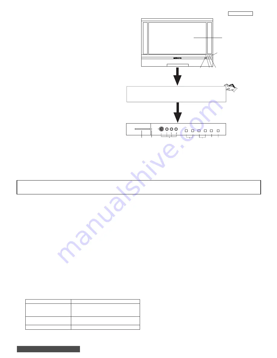
1.0 FRONT PANEL CONTROLS
INPUT 5
S-VIDEO
EXIT
INPUT
SELECT
MENU
VOL-
VOL+
CH-
CH+
VIDEO
AUDIO
L/MONO
R
PHOTO MC
PUSH
PUSH
MENU/SELECT button
This button allows you to enter the MENU, making it possible to set TV features to your preference without using the remote. This
button also serves as the SELECT button when in MENU mode.
INPUT/EXIT button
Press this button to select the current antenna source, VIDEO: 1, 2, 3, 4, 5 or alternate antenna source. Your selection is shown
in the top right corner of the screen. This button also serves as the EXIT button when in MENU mode.
CHANNEL selector
Press these buttons until the desired channel appears in the top right corner of the TV screen. These buttons also serve as
the cursor down (
) and up (
) buttons when in MENU mode.
VOLUME level
Press these buttons for your desired sound level. The volume level will be displayed on the TV screen. These buttons also serve
as the cursor left (
) and right (
) buttons when in MENU mode. When the TV power is turned OFF at a volume level 31 or greater,
the volume level will default to 30 when the TV is turned ON. However, if it is set to a level 30 or less, the volume level will be at
the level it was set when the TV is turned ON.
FRONT INPUT JACKS (INPUT 5)
Use these audio/video jacks for a quick hook-up from a camcorder or VCR to instantly view your favorite show or new recording.
Press the INPUT/EXIT button on the front control panel until VIDEO: 5 appears in the top right corner of the TV screen. If you have
mono sound, insert the audio cable into the left audio jack.
PHOTO MC
Insert a PC card adapter with your Photo memory card to view the digital still pictures (see page 44).
To view your digital pictures, an adapter is required. Below are adapters that are tested with your television. Please find out which
memory card you have and acquire it from your local source.
NOTES:
Your remote control does not have an INPUT button. To change to video inputs, press VID1~VID5 buttons depending
on your choice. To change antenna source, press the ANT button on your remote control.
Memory Card
Tested Samples
1. Secure Digital (SD)
Dazzle 4 in 1 (DM-9400)
3. Memory Stick (MS)
or
4. Smart Media (SM)
SanDisk 4 in 1 (SDDR-6507)
5. Compact Flash I (CF I)
Dazzle (DM-9000) or
6. Compact Flash II (CF II)
SanDisk (SDCF-38)
7. xD Picture Card
Olympus (MACF-10)
Notes: Adapter is subject to change for improvement.
Some terms used herein are trademarks of various companies.
BACK TO ADJUSTMENTS
Summary of Contents for 50V500 - UltraVision Digital - 50" Rear Projection TV
Page 12: ...12 LC37 LC37F I SPECIFICATION BACK TO ADJUSTMENTS ...
Page 14: ...14 LC37 LC37F I SPECIFICATION BACK TO ADJUSTMENTS ...
Page 15: ...15 LC37 LC37F I SPECIFICATION BACK TO ADJUSTMENTS ...
Page 16: ...16 LC37 LC37F I SPECIFICATION BACK TO ADJUSTMENTS ...
Page 17: ...17 LC37 LC37F I SPECIFICATION BACK TO ADJUSTMENTS ...
Page 20: ...20 LC37 LC37F I SPECIFICATION BACK TO ADJUSTMENTS ...
Page 95: ...95 LC37 LC37F BACK TO ADJUSTMENTS ...
Page 138: ......
Page 143: ......
Page 148: ...PRINTED CIRCUIT BOARD Control CS 148 LC3X BACK TO ADJUSTMENTS ...
Page 149: ...PRINTED CIRCUIT BOARD Control SS 149 LC3X ...
Page 150: ...PRINTED CIRCUIT BOARD Drive CS 150 LC3X ...
Page 151: ...PRINTED CIRCUIT BOARD Drive SS 151 LC3X ...
Page 152: ...PRINTED CIRCUIT BOARD DVI CS 152 LC3X ...
Page 153: ...PRINTED CIRCUIT BOARD DVI SS 153 LC3X ...
Page 154: ...PRINTED CIRCUIT BOARD Power CS 154 LC3X ...
Page 155: ...PRINTED CIRCUIT BOARD Power SS 155 LC3X ...
Page 156: ...PRINTED CIRCUIT BOARD Signal CS 156 LC3X ...
Page 157: ...PRINTED CIRCUIT BOARD Signal SS 157 LC3X ...
Page 158: ...PRINTED CIRCUIT BOARD Terminal CS 158 LC3X ...
Page 159: ...PRINTED CIRCUIT BOARD Terminal SS 159 LC3X ...
Page 160: ...CONNCETION DIAGRAM 160 LC3X ...
Page 161: ...BLOCK DIAGRAM 161 LC3X ...
Page 175: ...175 LC3X FINAL WIRING 1 of 4 BACK TO ADJUSTMENTS ...
Page 176: ...176 LC3X FINAL WIRING 2 of 4 ...
Page 177: ...177 LC3X FINAL WIRING 3 of 4 ...
Page 178: ...178 LC3X FINAL WIRING 4 of 4 ...
Page 182: ...181 Hitachi LCD Rear Projection TV Optical Engine Removal Procedure ...
Page 183: ...182 Pop off front grill Remove 4 screws holding front plastic piece w power button ...
Page 184: ...183 Left side close up Right side close up ...
Page 185: ...184 Remove 4 screws holding top cabinet front Left side close up ...
Page 186: ...185 Right side close up Remove screws holding lower rear cabinet ...
Page 187: ...186 Remove screws holding upper rear cabinet Remove 2 screws holding right subwoofer ...
Page 188: ...187 Pull out subwoofer as shown to access the upper cabinet wires Disconnect all the wires ...
Page 189: ...188 Now lift the top straight up 2 person lift Remove this bracket ...
Page 190: ...189 Bracket removed Next remove the Ballast Assy ...
Page 193: ...192 Remove the 5 screws holding down the Engine Assy Use a stubby 2 Philips head as needed ...
Page 195: ......


