background image

English   

- 5 -

DON’T 

place water filled vessels on top of T.V. cabi-

nets.

DON’T 

remove any fixed cover as this may expose

dangerous  voltages.

DON’T 

leave equipment switched on when it is unat-

tended  unless  it  is  specifically  stated  that  it  is  de-

signed  for  unattended  operation  or  has  a  stand-by

mode.  Switch off using the switch on the equipment

and make sure your family know how to do this.  Spe-

cial arrangements may need to be made for infirm or

handicapped people.

DON’T 

use equipment such as personal stereos or

radios  so  that  you  are  distracted  from  the  require-

ments of traffic safety.  It is illegal


to watch television

whilst  driving.

DON’T 

obstruct the ventilation of the equipment, for

example with curtains or soft furnishings.  Overheat-

ing  will  cause  damage  and  shorten  the  life  of  the

equipment.

DON’T 

use makeshift stands and NEVER fix legs or

stands to the TV with any screws other than those

provided - to ensure complete safety always use the

manufacturers  approved  stand  with  the  fixings  pro-

vided.

DON’T 

allow electrical equipment to be exposed to

rain or moisture.

ABOVE ALL

• NEVER  let  anyone,  especially  children  push

anything  into  holes,  slots  or  any  other  open-

ing  in  the  case  -  this  could  result  in  a  fatal

electric  shock.

•

NEVER guess or take chances with electrical

equipment of any kind - it is better to be safe

than  sorry!

1. Power

• Always use the provided AC adaptor.
• Operate only from the power source specified on

the AC adaptor.

• In use, the AC adaptor gets heat on the surface of

the case. It is normal, not defective.

• Do not cover the case of AC adaptor with any mate-

rial while it is in operation. Leave 15 cm space (mini-

mum) around the AC adaptor.

• The rating information and safety caution of the AC

adaptor are on its case.

Warning

: When the device is not in use for a long

time, disconnect from power.

2.Power Cord

Do not place the set, a piece of turniture, etc. on the

power  cord  (mains  lead)  or  pinch  the  cord.  Handle

the power cord by the plug Do not pull out the plug by

tugging  the  cord  and  never  touch  the  power  cord

when your hands are wet as this could cause a short

circuit or electric shock Never make a knot in the cord

or tie it with other cords. The power cords should be

placed in such a way that they are not likely to be

stepped on A damaged power cord can cause fire or

give you an electric shock. When it is damaged and

needs to be changed, it should be done by qualified

personnel.

3. Moisture and Water

Do not use this equipment in a humid and damp place

(avoid the bathroom, the sink in the kitchen, and near

the washing machine). Do not expose this equipment

to rain or water, as this may be dangerous and do not

place objects filled with liquids, such as flower vases,

on top of the set.Avoid from dripping or splashing. If

any solid object or liquid falls into the cabinet, unplug

the set and have 

it 

checked by qualified personnel

before operating it any further.

4. Cleaning

Before  cleaning,  unplug  the  adaptor  from  the  wall

outlet. Do not use liquid or aerosol cleaners. Use soft

and dry cloth.

5. Ventilation

The  slots  and  openings  on  the  back  cover  are  in-

tended  for  ventilation  and  to  ensure  reliable  opera-

tion. To prevent overheating, these openings must not

be blocked or covered in any way.

6. Heat and Flames

The set should not be placed near to naked flames

and  sources  of  intense  heat,  such  as  an  electric

heater. Ensure that no naked flame sources, such as

lighted candles, are placed on top of the set.

7. Lightning

In case of storm and lightning or when going on holi-

day, disconnect the power cord from the wall outlet.

8. Replacement Parts

When replacement parts are required, be sure the ser-

6XUHO\FRQQHFW

WKHJURXQGZLUH

Be  sure  to  ground  the  connection  properly.

Connect the ground terminal of the AC adaptor with the ground terminal provided at

the power outlet using the enclosed power cord. If the provided plug does not fit

your outlet, consult an electrician for replacement of the obsolete outlet.

01-ENG-2016-1243UK-17MB24-HITACHI-(LINE OUT-WO YPbPr)(LG-SDB1)-50098458.p65

11.01.2007, 17:45

5

Summary of Contents for 20LD2450

Page 1: ...GB N S Instructions for use Bruksanvisning Bruksanvisning 20LD2450 ...

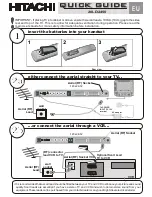
Page 2: ...a VCR Aerial RF Socket Aerial RF Socket wall socket wall socket Aerial RF Lead Aerial RF Lead Optional Scart Lead TV to VCR Aerial RF Socket VCR RF connector lead VCR to TV It is recommended that a scart lead should be fitted between your TV and VCR to enhance your picture and sound quality Scart leads are essential if you have a stereo TV and VCR and wish to obtain stereo sound from your equipmen...

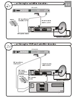
Page 3: ...IN ANT IN RF Lead to Aerial RF Lead to Aerial RF Lead from VCR to Satellite RF Lead from VCR to TV Satellite LNB lead Satellite LNB lead RF Lead from Satellite to TV Aerial Aerial VCR Scart Lead to on TV EXT 1 Scart Lead to EXT 1 on TV AV 1 TV TV VCR VCR AV 2 TFT LCD TV TFT LCD TV EU ...

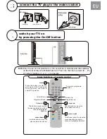
Page 4: ...lug Side View Programme Up Volume Up Volume Down Programme Down To select a programme number TV AV MENU P CH TV AV MENU P CH Cursor left This Button is used to move the menu selection box left or change a highlighted selection cursor down Use this button to move the menu selection box down cursor up Use this button to move the menu selection box up cursor right This Button is used to move the menu...

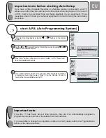
Page 5: ...re recorded tape and begin playback of your equipment These measures ensure that all your external equipment is tuned in during the Auto Setup procedure Auto Programming System Language Country English U K Check the antenna cable Auto Programming System Automatic tuning runs at 78 State Fine scanning Exit TV First select the language by using the or buttons on the remote control Use the or to sele...

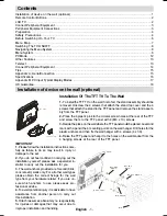
Page 6: ...the rear of the TFT and screw them to the TFT panel with 4 M4 x 10 screws 3 Decide the place on the wall where the TFT panel would be placed Level and mark with a pencil the 4 mounting points on the wall hanger Drill holes for the plastic anchors and then fix the wall hanger with 4 screws 4 x 30 4 Raise the TFT panel and hang it to the holes on the wall bracket from the 4 hanging screws at the rea...

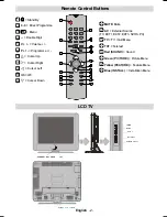
Page 7: ...or Up Cursor Right Cursor Left OK OK Cursor Down MUTE Mute AV External Source TV EXT1 EXT2 EXT3 SVHS PC TV TV Quit Menu TXT Teletext Red SOUND Sound Green PICTURE Picture Menu Yellow FEATURE Feature Menu Blue INSTALL Installation Menu 7 9 9 0 1 8 3 79 9 0 18 3 92 80 3 0 18 32 5 21 2 1 5 5 5 9 5 79 9 67 1 723 29 5 ...

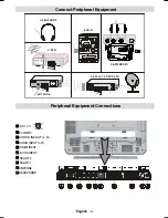
Page 8: ...l Equipment Peripheral Equipment Connections 17 1 8 2 1 5 9 2 1 1 287 1 287 3 21 8 2 9 2 6 7 7 5 9 5 17 11 0 25 5 DC 12 V 9 9 9 9 PCINPUT AUDIO LINE OUT L R AUDIO INPUT L R VIDEOINPUT S VHS INPUT SCART 2 SCART 1 ANTENNA HEADPHONE ...

Page 9: ...conforms to either ASTA or BSI BS1 362 approvals these are easily identifiable by either the or symbols If you are in any doubt about the installation of an extension lead please consult a competent electrician DON Ts DON T continue to operate the equipment if you are in any doubt about it working normally or if it is damaged in any way switch off withdraw the mains plug and consult your dealer Pr...

Page 10: ...re etc on the power cord mains lead or pinch the cord Handle the power cord by the plug Do not pull out the plug by tugging the cord and never touch the power cord when your hands are wet as this could cause a short circuit or electric shock Never make a knot in the cord or tie it with other cords The power cords should be placed in such a way that they are not likely to be stepped on A damaged po...

Page 11: ... product with about a million thin film transistors giving you fine picture details Occasionally a few non active pixels may appear on the screen as a fixed point of blue green or red Please note that this does not affect the performance of your product DO NOTLEAVE YOUR TVAT STAND BY OR OPER ATING WHEN YOU LEAVEYOUR HOUSE Before Switching On Your TV Power Connection IMPORTANT The TV set is designe...

Page 12: ...FN 0HQX LW 79 6281 0 18 3 785 0 18 785 6 0 18 167 0 18 9ROXPH DODQFH 6RXQG 0RGH 9 IIHFW TXDOL HU 0RGH 3 9ROXPH 6WRUH 3LFWXUH 0RGH ULJKWQHVV RQWUDVW RORXU 6KDUSQHVV RORXU 7 HPS 5RRP LJKWQLQJ 3LFWXUH RRP 6WRUH 6OHHS 7LPHU DQJXDJH KLOGORFN 7 2XWSXW 0HQX RORXU DYRULWH 0RGH 3URJUDPPLQJ 3URJUDPPH DQG KDQQHO 6WDQGDUG RORXU 6 VWHP 6HDUFK 9 5 0RGH HFRGHU 6WRUH 36 XWR 3URJUDPPLQJ 6 VWHP 7 W 5HJLRQ 3URJUDP 7...

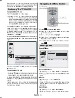
Page 13: ...nformation on this process see Install Menu section To switch the TV off Press the stand by button on the remote con trol so the TV will switch to stand by mode To power down the TV completely press Power On Off button or unplug the power cord from the mains socket The AC adaptor will still be active to completely dis connect the set from the mains remove the plug from the mains wall socket Naviga...

Page 14: ...e TV receives an NTSC signal Colour Temp By pressing a b button select Colour Temp Press _ to choose from one of these options Cool Normal and Warm RoomLightning By pressing a b button select Room Lightning By pressing button you can select one of these options Normal Bright and Movie Picture Zoom By pressing a b button select Picture Zoom Use _ buttons to change picture zoom to Auto 4 3 and Wide ...

Page 15: ...tandard to B G D K I or L L Colour System By pressing a b select Colour System Use _ button to change the colour system to PAL SECAM or AUTO Search By pressing a b select Search Press _ button to start search The search will stop when a signal is found Note If you press the buttons with one step moves a frequency of 0 25 Mhz will be advanced However if you press the buttons continually it will adv...

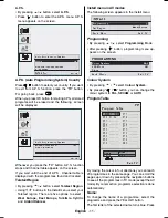
Page 16: ...menu select your Teletext region There are five options to select West Europe East Europe Turk Gre Cyrillic and Arabic Hebrew Install menu in AV modes The following screen appears in the install menu 167 3URJUDPPLQJ 7 W 5HJLRQ HVW XURSH DFN 0HQX LW 79 Programming By pressing a b select Programming Mode After pressing button programming menu ap pears on the screen 352 5 00 1 RORXU 6 VWHP 3 9 5 0RGH...

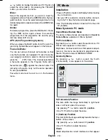
Page 17: ...de must be set to on in the features menu PC Mode Installation Power off both Computer and Display before making any connections Set your PC s resolution correctly before connect ing to the TV See the table on Appendix page Use 15 pin display cable to connect a PC to the LCD TV D SUB Menu System in PC mode Sound Menu Feature Menu The items in these menus are described in Sound Feature Menu explain...

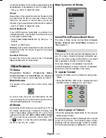
Page 18: ...ecreasing the volume level AV Modes By pressing the AV button you can switch your TV to AV modes except being in teletext Pressing this button consecutively will switch the TV in one of the optional AV modes TV EXT1 EXT2 EXT3 SVHS PC To remove source osd from screen press TV or button In order the quit the AV Mode press the TV or the P P button Menu System in AV Modes 6285 79 7 7 7 69 6 3 Sound Pi...

Page 19: ...ripheral Equipment Via The Scart The TV has 2 Scart sockets If you want to connect peripherals e g video decoder etc which have Scart sockets to the TV you can use SCART socket of the TV Note If an external device is connected via the Scart sockets the TV will automatically switch to AV mode If both sockets are employed at the sime time SCART 1 becomes the preferential Via Aerial Input If the devi...

Page 20: ...Picture Have you selected the correct TV system Is your TV set or house aerial located too close to non earthed audio equipment or neon lights etc Mountains or high buildings can cause double pic tures or ghost images Sometimes you can improve the picture quality by changing the direction of the aerial Is the picture or Teletext unrecognisable Check if you have entered the correct frequency The pi...

Page 21: ... TV S1 S20 S21 S41 NUMBEROFPRESETCHANNELS 100 CHANNELINDICATOR On Screen Display RF AERIAL INPUT 75 Ohm unbalanced OPERATING VOLTAGE 12V DC AUDIO German Nicam Stereo AUDIO OUTPUT POWER WRMS 10 THD 2 x 3 POWER CONSUMPTION W 60W 1 2 W Stand by PANEL 4 3 display 20 Screen Size DIMENSIONS mm HLJKW NJ LWK IRRW LWKRXW IRRW 0 16 216 PP ...

Page 22: ...isplay has a maximum resolution of 800 x 600 frequency range of 56 75 Hz The following table is an illustration of some of the typical video display modes RUL RQWDO 9HUWLFDO 0 9 0 9 9 6 9 6 9 6 9 6 9 6 9 6 9 6 9 6 9 6 9 6 9 6 5HVROXWLRQ UHTXHQF 2 3 7 2 1 0RGH ...

Page 23: ...ined or modified by any person other than an Hitachi authorised engineer iii The product serial number has not been removed or altered This guarantee does not apply to product acquired second hand or for commercial or communal use This guarantee does not cover the replacement of exhausted batteries the adjustment of user controls or aerial alignment Any parts replaced under this guarantee shall be...

Page 24: ...erservice italy hitachi eu com france consommateur hitachi eu com Digital Media Group 94 Quai Charles de Gaulles 69006 Lyon HITACHI EUROPE LTD Kodanska 46 101 00 Praha 10 CZECH REPUBLIC Tel 234 064 512 Fax 234 064 213 Email info hitachi be dmg eeu hitachi eu com HITACHI EUROPE S A 364 Kifissias Ave 1 Delfon Str 152 33 Chalandri Athens GREECE Tel 1 6837200 Fax 1 6835694 Email HITACHI EUROPE S A Gra...

Reviews: