background image

3

2.Appearance and structure

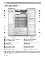
2 Appearance and structure

Note

:

Due


to


unceasing


modification


of


our


products

,

your


refrigerator may 

be slightly differant from this Services Manual,but its functions and using 
methods remain the same.

2.1 View of the appliance

Summary of Contents for BCD-535 W

Page 1: ...Refrigerator Service Manual M odel RC 70 W S4 S BC D 535 W...

Page 2: ...efrigerator compartment 6 Circuit and checking 6 1 Circuit diagram 6 4 Fan motor 7 Cooling system repairing 7 2 Summary of repair 7 3 Regulation of repair 7 4 Practical work of repair 7 5 Brazing refe...

Page 3: ...trical components when replacing them 7 Make sure the hook is correctly engaged Remove dust and foreign materials from the housing and connecting parts 8 Do not fray damage machine heavily bend pull o...

Page 4: ...e 2 Appearance and structure Note Due to unceasing modification of our products your refrigerator may be slightly differant from this Services Manual but its functions and using methods remain the sam...

Page 5: ...2 2 Wind channel structure 4 2 Appearance and structure Freezer Refrigerator Fan Wind input Air return...

Page 6: ...2 2 Wind channel structure 5 2 Appearance and structure Freezer Fan Refrigerator...

Page 7: ...2 2 Evaporator structure 6 2 Appearance and structure Sensor Evaporator Fuse Heater Accumulator Capillary...

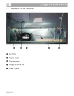
Page 8: ...7 2 2 Compressor room structure 2 Appearance and structure Dry filter Power cord Compressor Evaporation dish Water valve...

Page 9: ...ty freezer compartment L 168 Energy efficiency class A Climate class SN 10 32 C N 16 32 C ST 16 38 C T 16 43 C SN N ST T Refigerator room temperature C 2 8 Freezer room temperature C 24 14 Freezer com...

Page 10: ...ons have been touched and the doors are closed the backlighting will turn off after 60 seconds Caution When you set a temperature you set an average temperature for the whole refrigerator cabinet T em...

Page 11: ...10 4 Operation and functions...

Page 12: ...4 Operation and functions 11...

Page 13: ...4 Operation and functions 12...

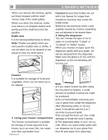
Page 14: ...4 2 Using the appliance 4 Operation and functions 13...

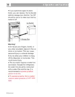
Page 15: ...4 Operation and functions 14...

Page 16: ...4 Operation and functions 15...

Page 17: ...4 Operation and functions 16 207 689 K...

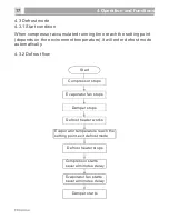
Page 18: ...vironment temperature it will enter defrost mode automatically 4 3 2 Defrost flow Compressor stops Evaporator fan stops Damper stops Defrost heater works Evaporator temperature reach the setting point...

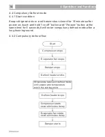
Page 19: ...same time for 5 seconds it will enter compulsory defrost mode after a long buzzing sound Compressor stops Evaporator fan stops Damper stops Defrost heater works 90 seconds later until evaporator temp...

Page 20: ...tions E4 Freezer temperature display area Defrost sensor malfunctions E0 Freezer temperature display area Environment sensor malfunctions E9 Freezer temperature display area Ice maker sensor malfuncti...

Page 21: ...ror display 4 Operation and functions 4 5 2 Checking method 4 5 2 1 Environment sensor error Start Change the display panel Is the sensor connecting wiring open circuit or short circuit Repair the wir...

Page 22: ...rt Change the mainboard Is the sensor connecting wiring open circuit or short circuit Repair the wiring Is the sensor OK Change the sensor Does the sensor connector plug well Plug the terminal well 4...

Page 23: ...n No 8 and No 12 on CN5 connector of mainboard 2 Freezer sensor corresponding pin No 9 and No 12 on CN5 connector of mainboard 3 Evaporator sensor corresponding pin No 10 and No 12 on CN5 connector of...

Page 24: ...of mainboard as the drawing below and repair if it is broken 2 Input 12V power to pin No 7 and No 8 on CN4 connector of mainboard check the ice maker can positive rotating Red wiring connect power whi...

Page 25: ...e display panel corresponding pin No 5 8 on CN7 connector of the mainboard as the drawing below Start Change the mainboard Is the connecting wiring between display panel and mainboard broken Repair th...

Page 26: ...al l Compressor running noises l Air movement noise from the small fan motor in the freezer compartment or other compartments l Gurgling sound similar to water boiling l Popping noise during automatic...

Page 27: ...cabinet may not be properly leveled or the draining spout underneath the top of the compressor depot may not be properly positioned to direct water into this pan or the water spout is blocked or the w...

Page 28: ...and clear of any obstruction l Is the water tank frozen because the refrigerator temperature is too low Try selecting a warmer setting on the display panel l Check if the filter is properly installed...

Page 29: ...r cord plugged into the power outlet Are mainboard terminals plugged well Is the compressor OK Plug the power cord well Change the mainboard Change the compressor Start Is mainboard output power OK Pl...

Page 30: ...as gap Change the door gasket Reassemble the door Is the door hanged down Is food palced too close to the sensor or cold air spout Explain not to place food too close to sensor or cold air spout Start...

Page 31: ...se OK Change the Temp fuse Is defrost heater OK Is there ice blockage on evaporator Do doors open frequently Explain not to open doors frequently Counsel to use colder temperature setting Change the d...

Page 32: ...Is freezer compartment OK Refer to 5 3 1 chapter Change the door gasket Is the door hanged down Reassemble the door Explain not to place food too close to sensor or cold air spout Explain not to open...

Page 33: ...appliance too close to heat sources Is watery or hot food stored in the cabinet Wipe out dew on the louver surface and run the refrigerator again 5 4 Thick frost in freezer compartment Start Reassembl...

Page 34: ...oes the door open too frequently Is the appliance too close to heat sources Is watery or hot food stored in the cabinet Advise to cool down hot food and seal watery food well before storing Make enoug...

Page 35: ...e Is the damper OK Change the damper Is the sensor OK Change the sensor Check the sensor connection and repair Counsel to use warmer temperature setting Start Is refrigerator temperature setting too c...

Page 36: ...35 5 Troubleshooting 5 7 Breaking of light Is the light disconnected or broken Is the door switch OK Change the door switch Check the door switch connection and repair Start Change the light...

Page 37: ...s the appliance leveled Level the appliance by adjusting the bottom feet Are the adjustable bottom feet broken Change the adjustable bottom feet Is the noise from compressor itself Add a rubber absorb...

Page 38: ...mp starts stops Is there sound from freezer compartment when compressor s running Fasten the evaporator Start Is there water flowing or hiss sound from the appliance Attache a gum absorber on the capi...

Page 39: ...fan itself or vibration when working Change the fan motor Is the fan damaged or transformed Is the fan touching surround Set the fan right avoid to touch surround Start Is the fan moving or shaking Ch...

Page 40: ...and repair Is pipe itself shaking strongly Is compressor itself shaking strongly Are pipes touching in the compressor room Separate the touching pipes Attach a gum absorber on top of the compressor S...

Page 41: ...40 6 Circuit and checking 6 1 Circuit diagram...

Page 42: ...er by screwdriver as picture 1 3 Remove the electric box cover as picture 2 4 Unplug the terminals on the mainboard as picture 3 5 Pry up the mainboard by fingers and take it out as picture 4 Picture1...

Page 43: ...y remove the electric box cover and check 2 Check the connecting wiring between compressor and mainboard and repair if it is broken 3 Use a multimeter to measure voltage between N label and COMP label...

Page 44: ...e 2 Remove the screws of protector box by screwdriver as picture 1 3 Pry up the protector box from top by screwdriver as picture 2 4 Unplug the overload protector as picture 3 5 Unplug the PTC starter...

Page 45: ...checking 1 Check the connecting wiring of fan motor is well or not repair if it is broken The fan motor corresponding pin No 13 15 on CN4 connector of mainboard as the drawing below 2 Pin No 14 connec...

Page 46: ...component and unplug the terminals as picture 2 4 Remove the screw of the wind channel component by screwdriver as picture 3 5 Pry up the wind channel cover from the buckles by screwdriver as picture...

Page 47: ...hecking 1 Check the connecting wiring of the damper is well or not repair if it is broken The damper corresponding pin No 1 6 on CN6 connector of mainboard as the drawing below 2 The damper will turn...

Page 48: ...as picture 1 3 Remove the wind channel component and unplug the terminals as picture 2 4 Separate the wind channel cover and foam as picture 3 5 Remove the sponge and adhesive paper on the foam as pi...

Page 49: ...7 connector of mainboard freezer light corresponding pin No 1 and No 3 ice maker light corresponding pin No 1 and No 4 as the drawing below 2 Check output voltage corresponding light of the mainboard...

Page 50: ...ppliance 2 Pry up the light cover from the buckles by screwdriver as picture 1 3 Remove the light cover as picture 2 4 Pry up the light from the buckles by screwdriver as picture 3 5 Unplug the termin...

Page 51: ...nector of mainboard freezer door switch corresponding pin No 4 and No 7 as the drawing below 2 Check the magnet on the door is dropped out or not 3 Normally when the door is closed the two pins of doo...

Page 52: ...ff temperature 72 Load voltage 250V Load current 10A 6 8 1 Basic parameters 6 8 2 Checking method 6 Circuit and checking Use a multimeter to measure resistance between the two terminals of the fuse if...

Page 53: ...picture 1 2 Remove the screws of evaporator by screwdriver as picture 2 3 Separate the evaporator component from the cabinet and remove the foams at left side and right side as picture 3 4 Cut the se...

Page 54: ...ultimeter to measure the voltage between pin No 1 and No 9 on XP7 connector of the mainboard if the voltage doesn t equal to electric supply power it means the heater is broken change it 2 Check the f...

Page 55: ...nals as picture 1 2 Remove the screws of evaporator by screwdriver as picture 2 3 Separate the evaporator component from the cabinet and remove the foams at left side and right side as picture 3 4 Cut...

Page 56: ...ng Refer to 4 5 Error display chapter 6 9 2 Removing the ice maker 6 9 2 1 Removing the ice bucket 1 Raise the ice bucket up as picture 1 2 Pull the ice bucket slantingly downwards as picture 2 3 Pull...

Page 57: ...ter intake 56 6 Circuit and checking 1 Pull the front cover out slantingly upwards as picture 1 2 Pull the water intake slantingly upwards as picture 2 3 Remove the two buckles of the water intake as...

Page 58: ...ice maker holder by screwdriver as picture 1 2 Unplug the terminal of the ice maker as picture 2 3 Remove the screws of the ice maker by screwdriver as picture 3 4 Remove the wiring as picture 4 5 Pul...

Page 59: ...Remove the screws of the motor by screwdriver as picture 1 2 Remove the coupling as picture 2 3 Remove the screws of the motor cover by screwdriver as picture 3 4 Remove the cover and pull out the mo...

Page 60: ...lug connecting terminal as picture 2 3 Remove the screws by screwdriver as picture 3 4 Pry up the ice dispenser at the buckles as pictire 4 5 Pull out the ice dispenser as picture 5 6 Unplug the motor...

Page 61: ...lve by screwdriver as picture 1 2 Pull out the water valve as picture 2 3 Unplug the connecting terminal as picture 3 4 Remove the water tube connector as pictire 4 5 Remove the water tube as picture...

Page 62: ...another then becomes middle temperature high pressure liquid after condensation Refrigerant enters dry filter water and imperity will be filtrated Refrigerant enters capillary and pressure will be red...

Page 63: ...62 7 Refrigeration system repair 7 1 Refrigeration system Anti condensation pipe Condenser Finned evaporator Compressor Dry filter Evaporation pipe Air return pipe Condenser...

Page 64: ...63 7 Refrigeration system repair 7 2 Summary of repair...

Page 65: ...64 7 3 Regualation for repair 7 Refrigeration system repair...

Page 66: ...65 7 4 Practical work for repair 7 Refrigeration system repair...

Page 67: ...66 7 4 Practical work for repair 7 Refrigeration system repair...

Page 68: ...wing 7 Refrigeration system repair Anti condensation pipe Condenser Capillary Air return pipe Dry filter Connecting pipe Connecting pipe Compressor Finned evaporator Evaporation pipe Refrigearnt flowi...

Reviews: