


19
WR6CE User Manual
Making Connections
Use of external interface of touch screen and selection of touch unit
This device has a TOUCH port. When you need to use an external PC as the touch unit and
signal source unit, you can connect USB ports of the device and PC with a USB cable (both
ends are male connections), connect the PC to the device with a signal cable (HDMI and
DP cable), and switch the signal source to that channel. At this time, the touch screen can
be connected to the corresponding unit, and the touch screen can be used to perform touch
operations on the unit.
On the home page, the device is used as the touch unit. In HDMI, OPS and DP channels, the
device is used as the touch unit by default. When the external unit is connected and powered
on, and the USB cable is connected to the external unit (OPS does not need a USB cable), the
touch unit is changed to the external PC.
To operate the device, you can use the five-point touch method to call out the soft control menu
and operate the device. After operation, tap any area out of the soft control menu of the device
to hide the soft control menu. Then you can continue to operate the external PC, and the
current channel is set as the touch input channel.
In the OPS channel, you can touch OPS without the soft control menu.
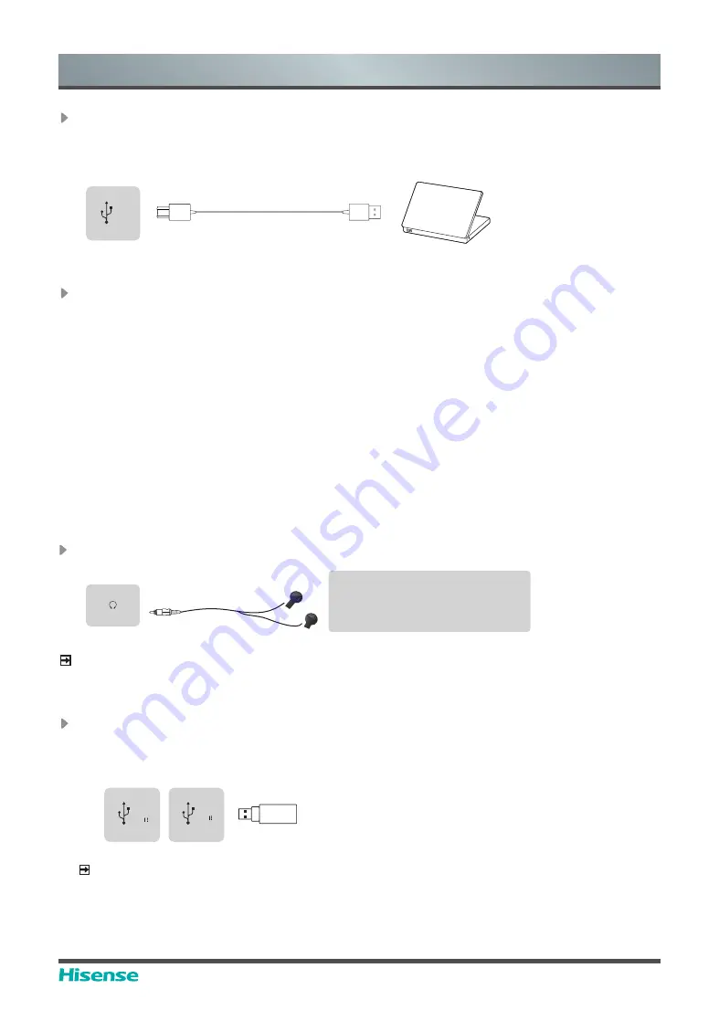
Connect to TOUCH interface device
It is the touch screen interface used for an external PC as touch host. In both the HDMI and DP
channels, the device is used as a touch unit by default
When connecting, USB cables not longer than 1 meter should be used to connect with the
external PC.
Device port
TO
UCH
USB
PC
Connect to a USB interface device
The total current of all the USB output ports of the device when connected to external devices
at the same time mustn’t exceed 2500mA, or else the device failure caused by overcurrent isn’t
covered by the warranty.
NOTE
This device is connected to wireless keyboard and mouse devices. If there is any insensitivity
phenomenon during use, you can try to change the wireless receiver to another USB port, or
use a USB extension cord to connect the wireless receiver in order to enhance the receiving
range.
External device
Device port
HEADPHONE
Connect Headphone for audio out of the screen.
Headphones (not included)
ATTENTION
Excessive sound pressure from
earphones and headphones can
cause hearing loss.
NOTE
Please make sure that the headphones you plug in is without microphone function, or it may not
be supported.
HEADPHONE
Device port
USB
DC 5V
1A(MAX)
USB
DC 5V
0.5A(MAX)


