background image

Video Settings

UM19H User Manual, 99155C, November 2022 

 19

Contrast / Brightness 

Menu

Description

Contrast

Adjusts the difference between the image background (black 

level) and the foreground (white level).

Brightness

Adjusts the background black level of the screen image.

Contrast / Brightness Menu

The Contrast / Brightness menu includes the Contrast and Brightness functions.

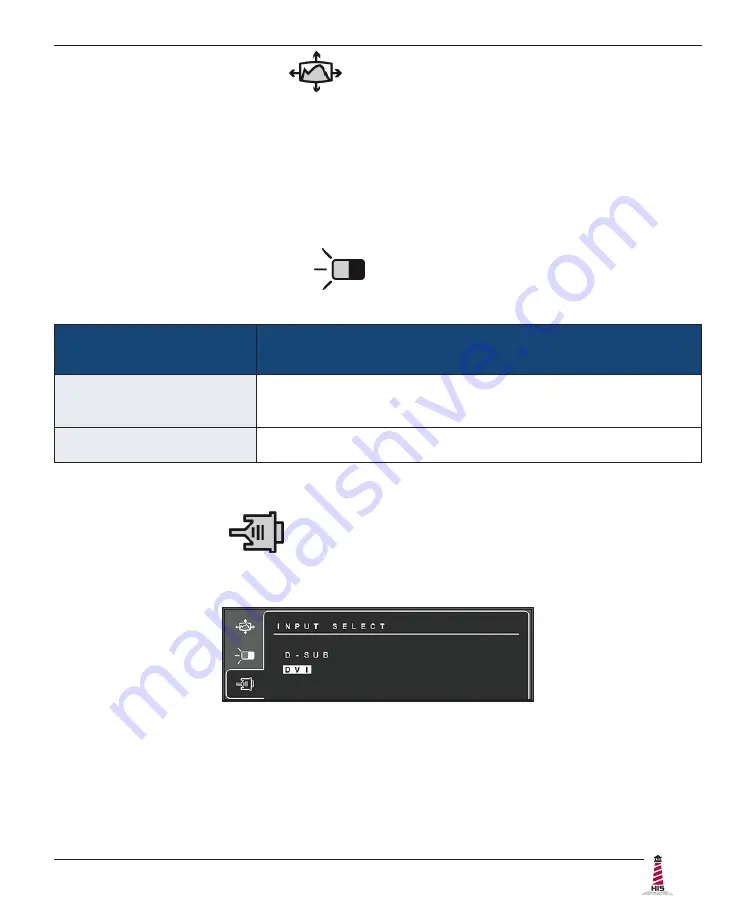
Input Select Menu

The Input Select menu allows the user to toggle between inputs if there is more than one 

computer connected to the display.  Use D-Sub for analog VGA signals and DVI for digital signals.

Auto Image Adjust Menu

The Auto Image Adjust menu automatically sizes, centers, and fine tunes the video signal to 

eliminate waviness and distortion�  Press button [2] outside of the OSD menu to activate Auto 

Image Adjust.

NOTE:

  Auto Image Adjust works with most common video cards.  If this function does not work 

on your display, lower the video refresh rate to 60 Hz and set the resolution to its pre-set value�

Summary of Contents for HIS-UM19-H Series

Page 1: ...USER MANUAL Model No HIS UM19 _ _ _ H REVISION H 19 UNIVERSAL MOUNT INDUSTRIAL MONITOR ...

Page 2: ... Assembled Workstations 11 Install Cable Exit Cover Plate 11 Mount the Monitor 12 Video Settings 15 Setting the Timing Mode 15 Control Panel Buttons 16 OSD and Power Lock Settings 17 On Screen Display OSD Menus 18 Auto Image Adjust Menu 19 Contrast Brightness Menu 19 Input Select Menu 19 Color Adjust Menu 20 Information Menu 21 Manual Image Adjust Menu 21 Setup Menu 22 Memory Recall Menu 23 Cleani...

Page 3: ...cessible DC Supplied Units only The HIS UM19 subject unit is to be powered by a Listed Power Supply suitable for the application with outputs at SELV LPS or Class 2 levels rated 9 6 36 6VDC 2 5 A max The equipment is not intended to connect directly to a DC Mains source FCC Notice This equipment has been tested and found to comply with the limits for a Class A digital device pursuant to Part 15 of...

Page 4: ...D Classe II Division 2 Groupes F et G et Classe III endroits hasardeux ou endroits non hasardeux seulement WARNING EXPLOSION HAZARD Do not disconnect equipment unless power has been removed or the area is known to be non hazardous WARNING EXPLOSION HAZARD Substitution of any components may impair suitability for Class I II III Division 2 Locations NOTE Hope Industrial Systems provides wiring and c...

Page 5: ...echanical Drawings UM19H User Manual 99155C November 2022 5 Mechanical Drawings Front View Rear View 467 4 mm 18 40 380 8 mm 14 99 397 5 mm 15 65 305 6 mm 12 03 CABLE ENTRY 467 4 mm 18 40 397 5 mm 15 65 ...

Page 6: ...ngs 6 UM19H User Manual 99155C November 2022 Side View 198 8 mm 7 82 34 3 mm 1 35 Side Mounting Holes 1 4 20 Internal Thread x 0 625 Deep 72 1 mm 2 84 KEYBOARD optional KVM EXTENDER optional 176 6 mm 6 95 124 5 mm 4 90 ...

Page 7: ...e that the air temperature around the unit top and bottom will not exceed the rated specifications of the unit f The maximum rated temperature for the HIS UM19 is 50 C 122 F f Remember that even though this product is designed to operate at 50 C the life span of any electronic device is shortened when it is consistently operated at high temperatures Therefore it is wise to take steps to keep the t...

Page 8: ... VGA port RGB BNC RCA HDMI and DisplayPort video sources require additional adapters After selecting the appropriate interface connect one end of your video cable to the input port on the rear of the monitor Secure the screw locks to ensure adequate strain relief Connect the other end to the appropriate port on your host computer or other video source HAZ LOC NOTE If this step is not performed the...

Page 9: ...sion 2 Hazardous Location requirements Connect and Set Up Touch Screen Applies to touch screen monitors only Instructions below apply to Windows systems Contact Hope Industrial Systems if you require a CD ROM with documentation and touch screen drivers For a full list of downloadable drivers please check the following address https www HopeIndustrial com support drivers IMPORTANT If you will be us...

Page 10: ...Connections Serial Connections must be made before installing the driver 1 Connect one end of the Serial cable to the Serial input port on the rear of the monitor Connect the other end to the Serial port on the host computer Tighten the screw locks on the cable connectors to ensure adequate strain relief HAZ LOC NOTE If this step is not performed the product will not comply with Class I II III Div...

Page 11: ...l com docs 99071 CP RG2 https www HopeIndustrial co uk docs 99120 Step 3 Install the Monitor Once you have completed the full bench test configuration and confirmed that all components are working properly you are ready for final installation and mounting of the monitor WARNING Hope Industrial will not assume liability for damage to internal electronics due to improper installation Contact Hope In...

Page 12: ...oducts and may also be found on our website at the following addresses Yoke Mounting Hardware https www HopeIndustrial com docs 99025 YB N12 KIT for YB _ _ BLK N12 Series https www HopeIndustrial com docs 99026 Yoke and Benchtop Mounting Kit for YB Series https www HopeIndustrial com docs 99027 Heavy Industrial Pedestal Mounts Our Yoke and Pedestal Mount allows full range of pan and tilt motion Co...

Page 13: ...rms for YA _ _ 15 and YA _ _ 24 Series https www HopeIndustrial com docs 99090 Wall Yoke for YW _ _ 07 Series https www HopeIndustrial com docs 99091 VESA Radial Arm The VESA Radial Arm Mount is designed to suspend our Universal Mount Monitors above a working area VESA Wall Mount Bracket The VESA Wall Mount Bracket allows simple effective mounting of our Universal Mount Monitors to any vertical su...

Page 14: ...d installation instructions for specific VESA mounting options are shipped with the product and may also be found on our website at the following address https www HopeIndustrial com docs 99034 If using VESA mounting screws not supplied by Hope Industrial Systems ensure they do not intrude into the enclosure more than 12 7 mm 0 5 IMPORTANT UNIVERSAL MOUNT MONITOR NYLON WASHERS RUBBER WASHERS M4 SC...

Page 15: ...de use the On Screen Display OSD controls to adjust the screen image TIP For the best picture quality set your computer graphics adapter timing mode to VESA 1280 x 1024 60 Hz Please refer to the computer graphics adapter manufacturer s manual for instructions on setting the resolution and timing mode In Microsoft Windows these settings may be found at the following location f 2000 XP Control Panel...

Page 16: ...nus and adjustments screens disappear automatically after 15 seconds This is adjustable through the OSD Time Out setting in the Setup menu 2 To select a control to adjust press the up or down button to scroll through the menu 3 Press button 2 to open the menu for a selected control 4 To adjust the control press the up or down button 5 To save the adjustments and return to the main OSD menu press b...

Page 17: ...d Shortcut to Auto Image Adjust When the OSD menu IS displayed Displays the control screen for the highlighted control Menu Opens the OSD menu Exits the OSD menu and saves adjustments OSD and Power Lock Settings f OSD Lock Press and hold 1 and the up button for 10 seconds If any buttons are pressed the message OSD Locked will display for 3 seconds f OSD Unlock Press and hold 1 and the up button ag...

Page 18: ...t and Brightness functions Input Select Allows the user to toggle between inputs Color Adjust Provides several color adjustment modes Information Displays the timing mode video signal input Manual Image Adjust Includes the H V Position Horizontal Size Fine Tune Sharpness Aspect Ratio ECO Mode View Mode and Blue Light Filter functions Setup Menu Includes the Language Select Resolution Notice OSD Po...

Page 19: ...he Input Select menu allows the user to toggle between inputs if there is more than one computer connected to the display Use D Sub for analog VGA signals and DVI for digital signals Auto Image Adjust Menu The Auto Image Adjust menu automatically sizes centers and fine tunes the video signal to eliminate waviness and distortion Press button 2 outside of the OSD menu to activate Auto Image Adjust N...

Page 20: ...een image for cooler white used in most office settings with fluorescent lighting Native Adds red to the screen image for warmer white and richer red Warm Adds red to the screen image for warmer white and richer red User Color Individual adjustments for red R green G and blue B 1 To select color R G or B press button 2 2 To adjust selected color press the up or down button NOTE If you select RECAL...

Page 21: ...sh rate is 60 Hz Manual Image Adjust Description H V Position Moves the screen image left or right and up or down Horizontal Size Adjusts the width of the screen image Fine Tune Sharpens the focus by aligning text and or graphics with pixel boundaries NOTE Try the Auto Image Adjust function first Sharpness Adjusts the clarity and focus of the screen image Aspect Ratio Selects the image size for 4 ...

Page 22: ...or different applications as well as the default Standard setting This feature may also be accessed by pressing the up button outside of the OSD menu Game adjusts the gamma curve to enhance darker scenes and improve visibility in brighter scenes Movie adjusts the contrast to enhances the black levels Web adjusts the gamma curve to improve contrast and color Text adjusts the color temperature contr...

Page 23: ...d For example with a 15 second time setting if a control is not pushed within 15 seconds the display screen disappears OSD Background Allows the user to turn the OSD background On or Off Auto Power Off When enabled this setting will automatically power off the monitor when no signal is detected for 3 minutes Power Indicator Allows the user to turn the Power Indicator light On or Off Memory Recall ...

Page 24: ... AS IT WILL SCRATCH THE PROTECTIVE COATING ALWAYS USE A SOFT CLOTH PREFERABLY MADE OF COTTON All displays may be cleaned using any standard glass cleaner as long as there is no abrasive or oily content Vinegar or ammonia will not hurt the screen The anti reflective coatings on glass window equipped displays are physically part of the surface of the glass and resist degradation ...

Page 25: ...ure the Power Indicator light is lit blue Check power connections at the monitor and power source For DC models check the connector polarity and ensure input voltage is 9 6 to 36 6 VDC The Auto Power Off function is enabled Disable the Auto Power Off function in the OSD s Setup menu No image on the screen and control s Power Indicator light is lit orange Video cable is not plugged in correctly Che...

Page 26: ...ly for the source signal Activate the Auto Image Adjust function in the OSD menu This function may also be activated by pressing the 2 button outside of the OSD menu Fine tune the picture by manually adjusting the image using the settings in the OSD s Manual Image Adjust menu Wrong or abnormal colors white is not white Monitor color settings are incorrectly adjusted Reset the monitor to the factor...

Page 27: ...etected until the touch screen driver is installed See section Installing the Driver Serial RS 232 Connections above Serial connection in use but connection to computer is not using the same port for which the touch screen driver is installed The Serial cable must be connected to the computer s COM port prior to driver installation to allow touch screen detection and association with the correct C...

Page 28: ...l 1000 1 static 20 000 000 1 dynamic Backlight typical LED 40 000 hour brightness half life Electrical Monitor Input AC power models 100 to 240 VAC 1 5 0 75 A 60 50 Hz DC power models 9 6 to 36 6 VDC 2 5 to 0 65 A Class 2 or SELV LPS Power Consumption 16 W Power Standby mode 0 5 W Environmental Operating Temperature 0 to 50 C 32 to 122 F Storage Temperature 20 to 60 C 4 to 140 F Humidity 20 to 90 ...

Page 29: ... Hz 1280 x 960 60 75 Hz 1024 x 768 60 70 75 Hz 800 x 600 56 60 72 75 Hz 720 x 400 70 Hz 640 x 480 60 75 Hz Response Time typical 14 ms Physical Enclosure Type Self contained enclosure Enclosure Rating Built to IP22 standards NEMA UL Type 2 Black Powder Coated or Stainless Steel Built to IP65 IP66 standards NEMA UL Type 12 4 Black Powder Coated Steel NEMA UL Type 12 4 4X Stainless Steel Enclosure D...

Page 30: ...NOM Registration No NOM 019 SCFI 1998 NOTE DC power must use shielded DC input cable Environmental IEC 60721 3 Reliability WEEE Registration No WEE DJ1859ZX for UK only Enclosure UL 50E File No E212889 Hazardous Location AC power models UL Rated for Hazardous Locations I T E Listed for Class I Division 2 for Groups A B C and D Class II Division 2 for Groups F and G Class III Temp Code T5 File No E...

Page 31: ... number must be conspicuously marked on the outside of the shipping box Hope Industrial Systems will not accept shipments not accompanied by the RMA number Except where otherwise noted you must ship or deliver the product to Hope Industrial Systems Freight prepaid What Does This Warranty Not Cover This warranty does not cover equipment which has been damaged due to misuse abuse or accident such as...

Page 32: ...9 800 001 0486 HopeIndustrial de Italy Phone 39 80 0740414 HopeIndustrial it Spain Phone 34 91 1438229 HopeIndustrial es Mexico Phone 52 800 9531935 HopeIndustrial mx EU Authorized Representative Falcons Logistics B V Hoeksteen 26 F 2132 MS Hoofddorp Netherlands HopeIndustrial eu Phone 31 20 241 0853 Sales sales HopeIndustrial eu Support support HopeIndustrial eu Accounting accounting HopeIndustri...

Reviews: