Hirschmann MACH104-16TX-PoEP+2X-E-L2P User Manual Download Page 28

28

Installation MACH104

Release 08 01/2019

Proceed as follows:

Take the SFP transceiver out of the transport packaging (1).

Remove the protection cap from the SFP transceiver (2).

Push the SFP transceiver with the lock closed into the slot until it latches 
in (3).

2.3

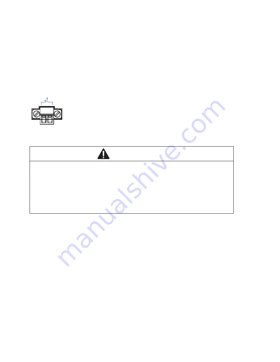
Wiring and installing the signal contact

Figure 11: 2-pin terminal block

Every

 time you connect the electrical conductors, make sure that the 

following requirements are met:

The electrical wires are voltage-free.

The connected voltage is limited by a current limitation device or a fuse.
Observe the electrical threshold values for the signal contact. 

See “General technical data” on page 37.

Remove the terminal connector from the device.

Connect the signal contact lines with the terminal block connections.

Mount the terminal block for the signal contact on the front of the device 
using the screw lock. Check whether the terminal block is correctly 
plugged and screwed on.

 
You find the prescribed tightening torque in chapter:

“General technical data” on page 37

 WARNING

ELECTRIC SHOCK

 
Never insert sharp objects (small screwdrivers, wires, or similar items) into 
the connection terminals for the signal lines, and do not touch the terminals.
 

Failure to follow these instructions can result in death, serious injury, 
or equipment damage.

FAULT

Summary of Contents for MACH104-16TX-PoEP+2X-E-L2P

Page 1: ...X F MACH104 20TX FR V 24 USB Aufkleber MAC Adresse P FAULT FAULT Sb RM 5 6 7 8 1 3 2 4 9 11 10 12 13 15 14 16 17 19 18 20 21 23 22 24 MACH104 20TX F V 24 USB Aufkleber MAC Adresse P FAULT FAULT Sb RM...

Page 2: ...performance features described here are binding only if they have been expressly agreed when the contract was made This document was produced by Hirschmann Automation and Control GmbH according to th...

Page 3: ...of them PoE ports 18 1 3 Supply voltage 19 1 3 1 MACH104 20TX F 19 1 3 2 MACH104 20TX FR 19 1 3 3 MACH104 20TX F 4 PoE 20 1 4 Ethernet ports 20 1 4 1 10 100 1000 Mbit s twisted pair port 20 1 4 2 100...

Page 4: ...e 31 2 5 Operating the device 32 2 6 Connecting data cables 32 3 Making basic settings 33 3 1 Default settings 34 4 Maintenance and service 35 5 Deinstallation 36 5 1 Removing the device 36 5 2 Removi...

Page 5: ...to work on the device Qualified personnel have the following characteristics Qualified personnel are properly trained Training as well as practical knowledge and experience make up their qualificatio...

Page 6: ...switch on the device when the casing is closed Relevant for North America Exclusively use 60 75 C 140 167 F or 75 C 167 F copper Cu wire Prerequisites All of the following requirements are complied w...

Page 7: ...conductor Regarding the properties of this fuse See Technical data on page 37 Relevant when the device is supplied via 2 voltage inputs Alternative 1 The total voltage supply meets the requirements fo...

Page 8: ...by the manufacturer are permitted to open the casing Never insert sharp objects small screwdrivers wires etc into the inside of the device Keep the ventilation slits free to ensure good air circulati...

Page 9: ...ket of electrical equipment designed for use within certain voltage limits In accordance with the above named EU directive s the EU conformity declaration will be at the disposal of the relevant autho...

Page 10: ...erence when the device is being used in a business environment The device creates and uses high frequencies and can also radiate these frequencies If it is not installed and used in accordance with th...

Page 11: ...circuit board assembly MACH104 20TX FR MACH104 20TX FR MACH104 20TX F 4PoE Equipment name Switch Model designation Power supply unit Note 1 Exceeding 0 1 wt and exceeding 0 01 wt indicates that the am...

Page 12: ...chanical stress Check for potential dangers resulting from unevenly distributed weight when you install the device in a switch cabinet Electric circuit overloading Observe the effects of electric circ...

Page 13: ...ernet on the Hirschmann product pages www hirschmann com Installation user manual Basic Configuration user manual Redundancy Configuration user manual Reference manual for the graphical user interface...

Page 14: ...14 Installation MACH104 Release 08 01 2019 Legend The symbols used in this manual have the following meanings Listing Work step Subheading...

Page 15: ...s work without a fan The following installation options are available 19 switch cabinet Mounting on a flat surface You have the option of choosing various media to connect to the end devices and other...

Page 16: ...V 24 interface for external management 6 See the following table column 1 7 See the following table column 2 8 Power supply connection on the back of the device 4 Gigabit Ethernet ports 4 Gigabit Eth...

Page 17: ...external management 6 See the following table column 1 7 See the following table column 2 8 P1 Power supply connection on the back of the device 9 P2 Redundant power supply connection on the back of...

Page 18: ...following table column 1 7 See the following table column 2 8 See the following table column 3 9 Power supply connection on the back of the device 10 Integrated PoE PSU on the back of the device 4 Gi...

Page 19: ...load is not distributed With redundant supply the standard power supply supplies the device on its own The redundant power supply becomes active automatically if the standard power supply fails Normal...

Page 20: ...port This port is an RJ45 socket The 10 100 1000 Mbit s twisted pair port allows you to connect network components according to the IEEE 802 3 10BASE T 100BASE TX 1000BASE T standard This port suppor...

Page 21: ...Full duplex mode Delivery state Autonegotiation activated 1 4 4 PoE ports The device variants MACH104 20TX F 4 PoE support Power over Ethernet PoE in accordance with IEEE 802 3af Figure Pin Function...

Page 22: ...of alternatively connecting a twisted pair cable via a RJ45 socket or an optical fiber via a SFP transceiver to a combo port By inserting a SFP transceiver you deactivate automatically the correspond...

Page 23: ...1 or 2 is on LED Display Color Activity Meaning P Supply voltage none Supply voltage is too low green lights up Supply voltage is on LED Display Color Activity Meaning Sb Stand by none Stand by mode n...

Page 24: ...per period Saves a configuration file from the storage medium ACA to the device flashes synchronously 1 per period Saves a configuration file from the device to the storage medium ACA LED Display Col...

Page 25: ...thermore the system monitor is available to you at the system start The AutoConfiguration Adapter ACA11 The interface casing is electrically connected to the front panel The V 24 interface is not elec...

Page 26: ...contact is open when the device is not connected to a power supply The signal contact allows you to control external devices or monitor device functions In the configuration you specify how the device...

Page 27: ...g the device Connecting data cables Note Note the safety instructions in Requirements for connecting electrical wires on page 6 2 1 Checking the package contents Check whether the package includes all...

Page 28: ...Observe the electrical threshold values for the signal contact See General technical data on page 37 Remove the terminal connector from the device Connect the signal contact lines with the terminal b...

Page 29: ...rface such as a table stick the supplied casing feet onto the bottom of the device with approx 0 8 in 2 cm of space from the corners If necessary remove any dirt from the bottom of the device where yo...

Page 30: ...he option to additionally fasten the device to the switch cabinet using 2 holding brackets on the back of the device You obtain the additional brackets as accessories See Accessories and order numbers...

Page 31: ...device See figure 14 You obtain the additional brackets as accessories See Accessories and order numbers on page 44 Fasten the device by screwing the brackets to the wall Figure 14 Vertical mounting o...

Page 32: ...f the device 2 6 Connecting data cables Note Verify that you connect only optical ports with the same optical transmission properties with each other Further information See Ethernet ports on page 20...

Page 33: ...ameters during the first installation Configuration via DHCP state on delivery Input via the V 24 interface Input via the HiView or Industrial HiVision application You find further information about t...

Page 34: ...te V 24 data rate 9600 Baud Ring redundancy disabled Ethernet ports link status is not evaluated signal contact Optical 100 Mbit s ports 100 Mbit s full duplex Other ports Autonegotiation Redundancy m...

Page 35: ...rschmann is continually working on improving and developing their software Check regularly whether there is an updated version of the software that provides you with additional benefits You find infor...

Page 36: ...brackets on the device Figure 15 Disassembling the device 5 2 Removing an SFP transceiver optional Figure 16 De installing SFP transceivers De installation sequence Proceed as follows Open the lockin...

Page 37: ...ss 0 15 4 W Power loss buffer 12 ms 115 V AC Overload current protection at input Non replaceable fuse Climatic conditions during operation Ambient air temperaturea a Temperature of the ambient air at...

Page 38: ...61000 4 2 Electrostatic discharge Contact discharge Air discharge 6 kV 8 kV IEC EN 61000 4 3 Electromagnetic field 80 MHz 3000 MHz max 20 V m IEC EN 61000 4 4 Fast transients burst Power line Data lin...

Page 39: ...Power line line line Power line line ground Data line 1 kV 2 kV 4 kV IEC EN 61000 4 6 Conducted disturbances 150 kHz 80 MHz 10 V EN 61000 4 9 Pulse magnetic fields 300 A m EMC interference emission EN...

Page 40: ...ng 3 dB system reserve when compliance with the fiber data is observed Fiber attenuation BLP Dispersion MM LC MM 1310 nm 50 125 m 0 dB 8 dB 0 mi 3 11 mi 0 km 5 km 1 0 dB km 800 MHz km MM LC MM 1310 nm...

Page 41: ...3 2002 Clause 38 single mode fiber offset launch mode conditioning patch cord 50 125 m 0 dB 10 5 dB 0 mi 0 34 mi 0 km 0 55 km 1 0 dB km 800 MHz km LX LC MM 1310 nme e With F O adapter compliant with I...

Page 42: ...ation Dispersion Type A LX LC EEC SM 1310 nm 1550 nm 9 125 m 0 dB 11 dB 0 km 12 43 mi 0 km 20 km 0 4 dB km 3 5 ps nm km Type B LX LC EEC SM 1550 nm 1310 nm 9 125 m 0 dB 11 dB 0 mi 12 43 mi 0 km 20 km...

Page 43: ...6 5 Power consumption power output MACH104device Maximum power consumption Maximum power output MACH104 20TX F 35 W 119 Btu IT h MACH104 20TX FR 35 W 119 Btu IT h MACH104 20TX F 4 PoE with 4 Class 0 P...

Page 44: ...ounted 1 Casing feet stick on 1 Non heating appliance cable Euro model Number Article 1 General safety instructions 1 Device 1 2 pin terminal block for signal contact 2 Brackets with fastening screws...

Page 45: ...00 Classic Switch software as of software version 04 1 00 HiSecOS as of software version 01 2 00 Do not use with the following devices SPIDER II MSP MSM EES Longer RSTP switching times and link loss...

Page 46: ...ly Gigabit Ethernet To set autocrossing manually is currently not possible M FAST SFP MM LC 943 865 001 M FAST SFP MM LC EEC 943 945 001 M FAST SFP SM LC 943 866 001 M FAST SFP SM LC EEC 943 946 001 M...

Page 47: ...er www hirschmann com in the product information Name CSA 22 2 No 60950 1 Information Technology Equipment Safety Part 1 General Requirements EN 61000 6 2 Electromagnetic compatibility EMC Part 6 2 Ge...

Page 48: ...Competence Center is ahead of its competitors on three counts with its complete range of innovative services Consulting incorporates comprehensive technical advice from system evaluation through netwo...

Page 49: ...Installation MACH104 Release 08 01 2019 49...

Page 50: ......

Reviews: