


2.5.1
Supply voltage (100 V AC ... 240 V AC, 50 Hz / 60 Hz)
Two 3-pin 7/8" plugs are available for the power supply to the device.
You find the prescribed tightening torque in
Technical data section on page
39
.
The supply voltage is connected to the device casing through protective ele-
ments exclusively.
Type and specification of
the supply voltage
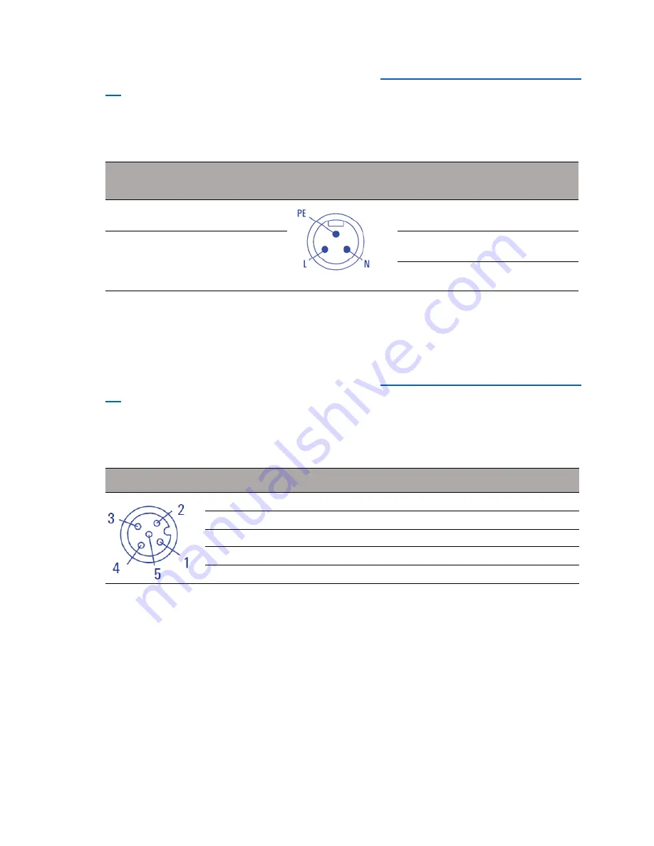
Connections
Rated voltage range AC
100 V ... 240 V, 50 Hz / 60 Hz
L
Outer conductor
Voltage range AC incl. maximum
tolerances
88 V ... 265 V, 47 Hz ... 63 Hz
PE
Protective conductor
N
Neutral conductor
Connect the electrical wires to the socket according to the pin assignment.
2.5.2
Signal contact
A 5-pin M12 plug is available as a signal contact.
You find the prescribed tightening torque in
Technical data section on page
39
.
Depending on the device variant, the signal contact lines are laid in the
power supply plug or in a special plug.
Connection assignments
1 —
2 Signal contact
3 —
4 —
5 Signal contact
Installation BATOne
Release 01 01/2019
30


