background image

7

(2)

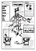
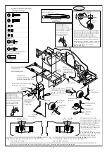
メインギヤのリンケージ

Main gear linkage

M2

ナット

M2 Nut 

ピボットボルト

Pivot Bolt

ピボットボルト

(

カラー付き

)

Pivot Bolt 
 with Collar

脚柱

φ

50

タイヤ

ストッパー

M3X3SS

引込脚ユニット

(

メインギヤ用

)

Retractable Gear Unit

M3X10CS

M4X4SS

M2

ナット

M2 Nut

脚柱

Wheel Shaft

Wheel Shaft

ストッパー

Stopper

Stopper

M3X3SS

φ

50Tire

φ

50

タイヤ

φ

50Tire

M3X12CS-TS

サーボ

サーボに付属のネジを
使用します。

Use the screws that 

came with the servo.

Servo

引込脚
サーボマウント

Servo Mount for 
Retractable Gear

ボールリンク
アジャストロッド

L=36

Ball Link Adjuster Rod L=36

13mm

ロック

Lock

5

°

ロック

Lock

引込脚ユニットは、飛行中や着陸の際に脚を
しっかり固定するようにロック機構がついて
います。このロック機構が十分機能するよう
にリンケージすることが重要です。
脚を引き込むと、少し角度が付きます。

メインギヤロッド

(2set)

MainGear Rod (2set)

The retractable gear unit is equipped with a locking 
mechanism that firmly locks the wheels in place 
during flight and for landing.  Linkage is important
 so that this locking mechanism functions properly.
When the retractable gears are retracted, 
there is a slight angle.  

ワンポイント

Important

20mm

approx. 20mm

36mm

M3X10CS

………………………

8

M3X12CS-TS

……………………

2

M2 nut

M2 

ナット

………………………

4

ピボットボルト

…………………

2

pivot bolt

ボールリンク

……………………

4

ball link

ピボットボルト

(

カラー付き

)

2

pivot bolt with Collar

M3X3SS

…………………………

2

M4X4SS

…………………………

2

カットします

Comes, out Retracted

Comes, out

Retracted

出る

引き込む

出る

引き込む

右 サーボの動作方向はノーズギヤと同じ方向

(NORMAL)

です。

Right

サーボの動作方向はノーズギヤと逆方向

(REVERSE)

になります。

Left

サーボを動作させ、ニュートラルで図の中立の位置にサーボホーンを取り付け、ロッドを取り付けた後に胴体に取り付けてください。

Activate the servo and position the servo-horn as shown in the figure.  Mount the fuselage after mounting the rod.

実際にサーボを動作させて、
ギヤが出た状態、引き込んだ状態で
ロックがかかることを確認します。
また、サーボの舵角が多い場合は
送信機側

(ATV.END.POINT

TRAVEL.ADJ

など

)

で調整します。

If the rudder angle is large, adjust using 
the transmission function (such as ATV
END.POINT.TRAVEL.ADJ). 

Confirm that the gear is locked both at 
retracted and protruded position 
when you operate the servo.

45

°

45

°

動作させた時に、
アジャストロッドが
引込脚ユニットに干渉
しない様に、

45

°傾けます。

動作させた時に、
アジャストロッドが
引込脚ユニットに干渉
しない様に、

45

°傾けます。

When operating, incline 45

°


so that the adjusting rod 
does not interfere with 
the retractable gears.  

When operating, incline 45

°


so that the adjusting rod 
does not interfere with 
the retractable gears.  

The operating direction of the servo is the same as 
the nose gear (normal).  

The operating direction of the servo is the opposite of 
the nose gear (reverse).  

95

°

JR NES-321, DS-3201

等を

使用する場合は

1

2mm

ットして下さい。

If using a JR NES-321 or 
DS-3201 servo, cut 1-2 mm 
to match its size.

Summary of Contents for BELL 222

Page 1: ... フレームの搭載 6 パーツリスト 7 マフラーの穴加工 5 付録 8 1 Nose gear linkage 2 Main gear linkage 4 5 6 7 10 11 12 13 14 15 16 Retractable gear linkage 2 Assembling the body 1 8 9 Floating rubber mounting 4 Disassembling the aircraft 3 Mounting the frame 6 Parts List 7 Preparing a hole for the muffler 5 Appendix 8 Contents 1 1560mm この度は60スケールボディ Bell222 をお買い上げ頂き誠にありが とうございます 取扱説明書に従い 組立を行って下さい Sold separately Small ser...

Page 2: ...及びシリコン部品の洗浄には使用出来ません RCアルコールスプレー グローエンジン内部及びシリコン部品にも使用出来ます 飲用不可 RCほこりとばしスプレー 強力エアーでほこりを一発除去 RC冷却スプレー 瞬間的にマイナス温度に冷却 エンジンのオーバーヒート ニッカドバッテリーの急速冷却に有効 RCグリススプレー たれ落ちないグリス 垂直面にも RC防錆潤滑スプレー さらっとした防錆潤滑剤 イージーエポ FRP用 両面テープ 厚さ 1mm 2mm 1mm and 2mm thick double sided adhesive tape 525 500 1 050 1 000 945 900 1 050 1 000 1 260 1 200 1 890 1 800 1 890 1 800 840 800 840 800 1 365 1 300 2 625 2 500 1 050 1 000 840...

Page 3: ...r Setting is easier by mounting two or three control units for the servo motor on one channel depending on the number of unused channels for transmission Available Units Futaba Multi servo Adjuster JR Multi box Example If there are three open channels Connect each servo to the receiver and mix the programs If there are two open channels If using a branch device that does not have the rudder adjust...

Page 4: ... 接着後ø3穴加工 Drill ø3 mm holes after affixing エポキシ Epoxy エポキシ Epoxy エポキシ Epoxy エポキシ Epoxy ダウエルピン Dowel pin ローレット Knurled 丸い方 Round 10X10ベニヤ板 10X10 plywood 接着後ø3穴加工 Drill ø3 mm holes after affixing ブラケット Bracket エポキシ Epoxy エポキシ Epoxy エポキシ Epoxy エポキシ Epoxy 内側から網を貼ります Affix the nets from the inside 生地完成キットは組立を行って下さい Assemble the unpainted completed body kit ポイント point 接着が完全に出来る様 FRPの接着面はサンドペーパー等で サンディング...

Page 5: ...3 nut FW3X8X0 5 クロスします エポキシ Epoxy エポキシ 3 水平 垂直尾翼の取付 Installing the Horizontal Stabilizer Vertical Fin and Exhaust Pipe 5 M3X20ボタンボルト FW3X8X0 5 M3ナット M3 nut 1 M3X20 Button Bolt M3X16ボタンボルト 1 M3X16 Button Bolt 2 4 2 ボディの組立 Assembling the fuselage 網をカットし 貼付けます Cut the net sections and affix them 排気管 Exhaust pipe 10X10ベニヤ板 10X10 plywood テールスキッド Tail skid テールスキッド Tail skid 約25mm Approx 25 mm ø2 5 2 7穴 ...

Page 6: ...came with the servo φ45タイヤ Tire 脚柱 Wheel Shaft ストッパー Stopper M3X3SS M4X4SS M2ナット M2 Nut 引込脚ユニットを動かしてみて ケースに接触 しない位置まで差し込みます Move the retractable gear unit to insert it into a position where it will not touch the case 引込脚ユニット ノーズギヤ用 Retractable Gear Unit Nose Gear M3X10 CS ピボットボルト Pivot Bolt ピボットボルト カラー付き Pivot Bolt with Collar ボールリンク Ball Link サーボの舵角が 多い場合は送信機 側 ATV END POINT TRAVEL ADJなど で調整します ア...

Page 7: ... bolt with Collar M3X3SS 2 M4X4SS 2 カットします Comes out Retracted Comes out Retracted 出る 引き込む 出る 引き込む 右 サーボの動作方向はノーズギヤと同じ方向 NORMAL です Right 左 サーボの動作方向はノーズギヤと逆方向 REVERSE になります Left サーボを動作させ ニュートラルで図の中立の位置にサーボホーンを取り付け ロッドを取り付けた後に胴体に取り付けてください Activate the servo and position the servo horn as shown in the figure Mount the fuselage after mounting the rod 実際にサーボを動作させて ギヤが出た状態 引き込んだ状態で ロックがかかることを確認します また サー...

Page 8: ...にジャイロをのせないで下さい トップカバーに接触します Disassembling the Aircraft 機体の分解 3 Cut the top portion using a file Do not place the gyro here It must not touch to the top cover エルロンロッド エレベーターロッド Aileron rod Elevator rod トップカバーに接触しますので 上側のエルロンロッド エレベーターロッドを 内側へ付け替えます ø5ボール ø5 ball ø5ボール ø5 ball X型レバー X type lever サーボホーン Servo horn Switch the upper aileron rod and elevator rod to the inside so that they will not touch...

Page 9: ...he frame and body and determine the hole position for the muffler exhaust port Remove the frame again and use a router or file to open a hole for the exhaust Preparing a Hole for the Muffler マフラーの穴加工 4 M3X8CS カット Cut off 4 M3X8CS M3X8CS Fuselage Frame If the muffler touches the fuselage frame use a cutter file etc to cut away part of the fuselage frame Temporarily fasten the floating rubber ø22 to...

Page 10: ...m 198mm 203mm 17mm 17mm 17mm ø3 2穴加工 ø3 2 hole drilling 前方 FRONT 5 接着剤 セメダインスーパーX Position with the hole for the body frame mounting and glue the floating rubber ø22 to the body The long screws should penetrate all the way through to make positioning easier Always use Cemedine Corporation Super X glue To protect the rubber apply glue to the side surface After thoroughly gluing the surface for adhe...

Page 11: ...3 Nylon Nut M3X8CS 4 M3X6CS 4 M3X20CS 4 M3X20CS Body stay L42 Body stay L42 Temporarily insert the frame into the body To protect the rubber apply glue to the side surface Mount the floating rubber ø22 and body stay L42 4 ボディの中でボディステーL42を組み合わせて フローティングゴムø22をボディの内側に接着します 接着剤は必ずセメダイン工業スーパーXを使用して下さい 接着剤が十分に硬化するまで放置して下さい Position with the body stay L42 in the body and glue the floating rubber ø22 to t...

Page 12: ... ラダ ロッド Rudder Rod フレームをボディから取り外す際 及び搭載する際 は これら3ヶ所の ボディステーL42を Lレンチを使い ボディの中で取り外し 取り付け を 行って下さい When removing the frame from the body or when mounting it use an L wrench to remove or to mount the three body stays L42 M3ナイロンナット M3 Nylon Nut FW3X9X1 M3ナイロンナット M3 Nylon Nut M3ナイロンナット M3 Nylon Nut FW3X9X1 FW3X9X1 FW3X9X1 M3X8CS M3X8CS M3X8CS M3X10CS FW3X9X1 FW3X9X1 M3X10CS M3X10CS テールパイプ Tail pipe M3ナ...

Page 13: ...s of the FREYA フレイヤ付属 Provided to the FREYA 生地完成キットはネジの 塗装はしておりません The screws in the competed body kit have not been painted フ レイ ヤ付属 Provided to the FREYA 生地完成キットの場合 ウイ ンドウはケガキ線を目安にカ ットして下さい 少し大きめに切って ボディ に合わせて修正するとよいで しょう When using the unpainted completed body kit cut the window along the mark off line Cutting it slightly larger than necessary and then adjusting it so that it fits the body is b...

Page 14: ...引込脚セット 60Airwolf landing gear set フローティングゴムφ22 T9 5 Floating rubber φ22 T9 5 ボディステーL42 Body stay L42 M2 ナット M2 nut M3 ナイロンナット Ps ball link S ヒラワッシャー 3X9X1T アジャストロッド M2X35 Adjust rod M2X35 Substitute for adjust rod M2X36 セットスクリュー M3X3 Set screw M3X3 キャップスクリュー M3X6 Cap screw M3X6 キャップスクリュー M3X8 Cap screw M3X8 Cap screw M3X10 キャップスクリュー M3X10 キャップスクリュー M3X20 Cap screw M3X20 Flat washer 3X9X1T M3 nylon...

Page 15: ...Part 60ベル222 尾翼セット 60 BELL222 fin set 入数 Q ty 1式 1 set 26 250 25 000 60ベル222 テールコーン 60 BELL222 tail cone 1式 1 set 6 300 6 000 60ベル222 ウィンドウセット 60 BELL222 window set 1 19 950 19 000 0412 276 引込脚用T型レバー T type lever for retract 3 1 680 1 600 税込価格 税抜価格 円 Price Yen 備考 Remarks 0412 276 15 受注生産 Made to order 受注生産 Made to order 受注生産 Made to order ...

Page 16: ...EYA の場合 When using with the sst eagle FREYA EX or EX WC sst eagle FREYA EX EX WC 使用しません Not used for Bell222 使用しません Not used for Bell222 Not used for Bell222 使用しません M3ナイロンナット M3 nylon nut テールスポンジ Tail sponge FW3X9X1 M3X20CS M3X35CS EXフローティングアングルを使用の場合 フレーム下側は付属のフローティングゴムを使用してください Bell222に付属のフローティングゴム 22は側面のみ使用します SX L アングルを使用の場合 sst eagle FREYAと同様にフレーム下側にフローティングゴム 22の取り 付けを行ってください ボディステー L42取付位置 B...

Page 17: ...ングアングルでは 後ろ側の出っ張り部分がボディに干渉します カットするか もしくは0404 820EXフローティングアングルに 交換してください 入数 Qty EX Floating angle 1set EXフロ ティングアングルセット 0404 820 9800 10290 1式 Price Yen 税込価格 税抜価格 円 コード 品 名 備 考 使用しません Not used for Bell222 使用しません Not used for Bell222 FW3X9X1 FW2 6X7 5X0 5 FW3X9X1 M3X6CS FW3X9X1 M3X6CS M3X35CS M3X6 Button bolt テールスポンジ Tail sponge FW3X9X1 M3X8CS ボディステー L42取付位置 Body stay L42 attachment position EXフローテ...

Page 18: ...MEMO MEMO MEMO MEMO MEMO ...

Page 19: ...MEMO MEMO MEMO MEMO MEMO ...

Page 20: ...たら ご一報くださいますようお願いいたします 運用した結果については 項にかかわらず責任を負いかねますので ご了承ください Reproduction of this manual or any part thereof is strictly prohibited The contents of this manual are subject to change without prior notice Every effort has been made to ensure that this manual is complete and correct Should there however be any oversights mistakes or omissions that come to your attention please inform us Item not wit...

Reviews: