background image


HIOTH TECHNOLOGY CO., LTD.


  USER MANUAL


www.HiotH.com 

Notes for the diagram: 

L

- terminal for live lead 

N

- terminal for neutral lead 

L

1

-output terminal of load (controlling connected lighting device, or other load) 


INSTALL THE SWITCH BASE 

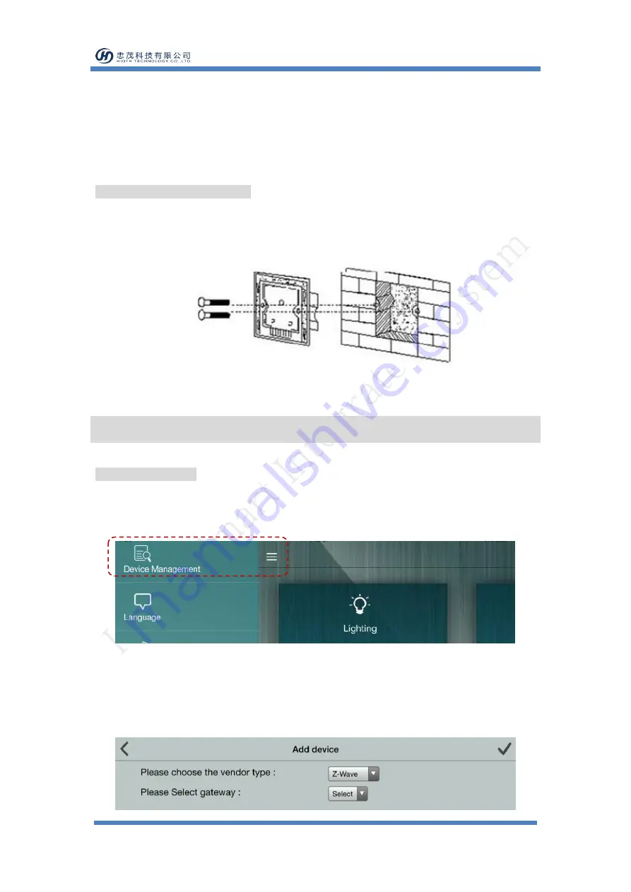
As shown in Fig.3, install the touch switch inside the wall box after wiring, then screw up to make 

it fixed on the wall. Put the base to the wall as well as cover and press the touch panel. 


Fig.3 

Operation  

NETWORK ENTRY 

1)


Please follow the below menu order on APP to find the network join interface: 

Log in > Menu bar > Device Management > Add device 


2)


Connect the power supply, and make sure that device in a state of "No node ID". 

3)


Press and hold any key on the panel for 8 seconds (INDICATION LED on the panel will turn 

green.). 

4)


Choose "Z-Wave" to enter the Network Inclusion mode on the APP, then click "

". 


Summary of Contents for CT-LCZW5026-MH

Page 1: ...ol as well as combines with other devices to do more settings such as scenarios linkage control The touch panel switch has a beautiful and concise appearance and for the US regulatory dimen sion and can be directly replaced the ordinary wall switch to reduce the cost and time of rewiring Technical Information Local touch panel and mobile terminal control Replace the traditional switch retain the o...

Page 2: ...0mm 75mm 38mm Installation Instructions PRODUCT INSTALLATION CAUTION Cut off power supply at circuit breaker or fuse before installation to avoid fire or shock Neutral and live wire are required to put into the bottom box 1 As shown in Fig 1 using the screwdriver to pry the gaps on the side of the switch then open the panel Fig 1 2 Using both hands to hold the switch panel and forcibly push up to ...

Page 3: ...n screw up to make it fixed on the wall Put the base to the wall as well as cover and press the touch panel Fig 3 Operation NETWORK ENTRY 1 Please follow the below menu order on APP to find the network join interface Log in Menu bar Device Management Add device 2 Connect the power supply and make sure that device in a state of No node ID 3 Press and hold any key on the panel for 8 seconds INDICATI...

Page 4: ...peat steps 2 5 If the device Online directly perform steps 1 5 Offline disconnect the device first and then perform steps 1 5 Safety Notice A qualified electrician with the understanding of wiring diagrams and knowledge of electrical safety should complete installation following the instructions Before installation please confirm the real voltage complying with the device s specification Cut off a...

Reviews: