background image

36

Screen of Administration

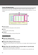
Select this screen in the menu of [Setting] of Connection screen to control set values of the 
screwdriver from the PC. For each screw fastening term, you send a file after reading it or save the 
changes.

Setting channels

You can control up to four patterns at the same time.

Port list

Select the port to send the setting.

Set button

The setting is sent to the port selected in the port list.

How to save setting

1

Click the [Setting] menu.

The connection with the screwdriver is cancelled.

2

Change the setting item if necessary.

 The items are the same as those on the setting screen. For the details, refer to“Sending Command” 
(P. 33).

3

Select [Save As] in the [File] menu to decide where to save the data.

The file path for the setting data is remembered.

 4 patterns are saved in a file. If you want to save 5 or more patterns, create another file name.

Summary of Contents for BLG-4000BC2

Page 1: ...ET A011 BC2 19A Operation Manual 2019 7 Built in screwdriver Pulse system BLG BC2 Series BLG 4000BC2 BLG 4000BC2 LT BLG 5000BC2 BLG 5000BC2 15 BLG 5000BC2 18 BLG 5000BC2 HT BLG 7000BC2 ...

Page 2: ... Screw Counter Minimum Pulse Maximum Pulse Work Reset Timer Count Timer for Reverse Rotation System Pulse Detection Total Torque ups count Inactive Time of Torque up 26 Connecting the Special Cable Option Checking Supplied the Cable Accessories BLG BC2 3010 BLG 4000BC2 BLG 5000BC2 Series BLG BC2 3012 for BLG 4000BC2 LT BLG 7000BC2 Connecting to Screwdriver BLG 4000BC2 BLG 5000BC2 Series Connecting...

Page 3: ...rwise it may cause a fire or an electric shock Do not connect anything other than specified to the connection part of this device Otherwise it may cause an electric shock or a failure Handling Do not wear clothes with flippers on the cuffs gloves neckties etc Otherwise they may get caught in the rotating screwdriver and cause an injury or a failure Wear suitable clothing and protective eye wear fo...

Page 4: ... operate the screwdriver with wet or oiled hands Do not operate the FOR REV switch before the screwdriver completely stops Otherwise it may cause a failure Do not disassemble remodel this device Otherwise it may cause a failure Maintenance and Inspections Turn off power and remove the power plug from the outlet when the device is not in use for a long time Remove the accessories from the screwdriv...

Page 5: ...G 4000BC2 LT BLG 4000BC2 BLG 5000BC2 BLG 5000BC2 15 BLG 5000BC2 18 BLG 5000BC2 HT BLG 7000BC2 Bit Drive H4 0 Ø2 0 40mm 0 Ø2 5 40mm 0 Ø2 5 40mm 1 Ø4 0 40mm 1 Ø4 0 40mm 2 Ø4 0 40mm Bit Drive H5 1 Ø5 0 60mm 2 Ø5 0 60mm 1 Ø5 0 60mm 2 Ø5 0 60mm Bit Drive 1 4 HEX 1 Ø5 0 50mm 2 Ø5 0 50mm Ø5 0 50mm Hexagon L shaped wrench 5 mm across flats BLG 5000BC2 Series BLG 7000BC2 Only ...

Page 6: ...ct the screwdriver cord to the power unit and the screwdriver Use the joint ring for fixing to prevent the cord from coming off 2Connect the power unit cord to the power unit and the outlet and turn on the switch The indicator on the power unit turns on ...

Page 7: ... the screwdriver BLG 5000BC2 Series BLG 7000BC2 Attach the bit while pulling out the joint shaft collar from the screwdriver BLG 4000BC2 BLG 4000BC2 LT BLG 5000BC2 BLG 7000BC2 2Confirm the bit has been attached firmly by pulling it light Precaution for Use of Hexagonal Bit You cannot use a double head bit with double grooves Prepare suitable sockets for those bits Bit Socket 5HEX 5 mm across flats...

Page 8: ...press it into an object BLG 5000BC2 Series 1Remove the switch lever Remove the shaft screw Be careful not to lose the lever spring 2Change the start mode Use something pointy such as a pen 3Re attach the shaft screw Caution Do not give a strong impact to the start mode switch Otherwise it may cause a failure Do not use the screwdriver while the shaft screw is not fixed Otherwise it may cause a fai...

Page 9: ...09 BLG 7000BC2 1Remove the switch lever Remove the shaft screw Be careful not to lose the lever spring 2Turn over the switch lever and attach it 3Re attach the shaft screw ...

Page 10: ...0BC2 Series REV 0 FOR BC2 COUNT CONTROL PASS Fail M 8 6 4 2 BLG 5000BC2 Series REV 0 FOR 3 1 5 7 BC2 COUNTCONTROL Fail PASS M BLG 7000BC2 BC2 COUNTCONTROL Fail PASS M 3 1 5 7 9 REV 0 FOR Parts and Their Functions ...

Page 11: ...his is to connect the screwdriver to the power unit The plug on one end is the same as that on the other end Hanger This is used to hang the screwdriver from the balancer FOR REV switch You can change the rotational direction with this switch FOR Clockwise 0 Neutral REV Counterclockwise Adjustment scale of torque This is used as a guide for output torque adjustment For details refer to Setting the...

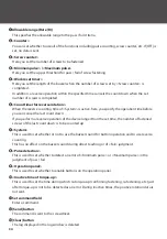
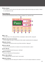
Page 12: ...splay This displays the number of pulses the operational conditions of the screw counter error conditions and etc In addition you follow the instructions on the display during setup M indicator This turns on when operations on the button are inactive In addition it blinks in the mode of temporary fastening option PASS indicator This turns on when the result of fastening a screw is accepted Fail in...

Page 13: ...er starts the pulse is counted and PASS Fail is indicated by the sound and the indicator PASS Fail M PASS Fail M In case of over 1000 pulses is displayed For details of how to set pass fail refer to Setting the Pass Fail Criteria P 17 When a screw is seated the clutch is activated to stop rotation If you restart the screwdriver the PASS Fail indicator turns off How to Change Rotation Speed When yo...

Page 14: ...es Use the torque meter by HIOS to check the torque precisely BLG 4000BC2 Series 1Remove the protection cover of the torque adjustment nut 2Turn the torque adjustment nut to set the fastening torque Adjust the edge face of the torque adjustment nut to come right above the scale For BLG 4000BC2 LT adjust the edge face of the nut fixing ring to come right above the scale When the nut fixing ring s p...

Page 15: ...Spring on the device Spring in the accessories How to Change to Smaller Torque If you use the torque adjustment spring in the accessories you can change the torque value smaller Change the spring depending on the work conditions 1Remove the torque adjustment nut and the spring holder and replace the torque adjustment spring 2Re attach the torque adjustment nut and the spring holder Attach the spri...

Page 16: ...th the scale Output Torque Guide HI Input BC2 15 BC2 15 BC2 18 BC2 18 BC2 HT BC2 HT 5000BC2 5000BC2 Torque scale 1 0 2 0 6 0 4 1 0 0 8 1 2 N m N m N m N m 2 3 4 5 6 7 8 7000BC2 7000BC2 Torque scale 0 7 1 5 1 1 2 3 1 9 2 7 2 8 N m Torque scale 1 0 5 0 7 1 1 1 3 0 9 1 5 2 3 4 5 6 7 8 Torque scale 1 0 5 0 7 0 9 1 1 1 3 1 5 1 7 1 9 2 0 2 3 4 5 6 7 8 Torque scale 1 0 3 0 4 0 6 0 8 1 0 2 3 4 5 6 7 8 2 3...

Page 17: ...esholds for pass fail Considering the measurement errors you can set allowable ranges on thresholds 90 91 131 99 119 132 Allowable range 10 Allowable range 10 The number of pulses during teaching Fail PASS Fail Pulse Pass fail range Example Minimum pulse 100 Maximum pulse 120 Allowable range 10 Caution Do not use the conditions i e screws workpieces etc for teaching different from those of real op...

Page 18: ...eshold PASS Fail M Every time you press the F3 button the allowable range changes 0 5 10 15 20 0 4Press the F1 button to confirm the allowable range The number of pulses is changed to the one with the tolerance factor calculated on both thresholds PASS Fail M PASS Fail M 5Press and hold the F2 button PASS Fail M The buzzer starts to indicate setting is finished The number of screws to be fastened ...

Page 19: ... Fail M If you press the F3 button the number of the selected digit is changed If you press the F2 button you can move to another digit The third digit is displayed by scrolling on the screen 3Press the F1 button to select Maximum Pulse and enter your target number PASS Fail M If you press the F3 button the number of the selected digit is changed If you press the F2 button you can move to another ...

Page 20: ...nother digit Enter a quantity from 1 to 99 PASS Fail M PASS Fail M 3Press and hold the F1 button The buzzer starts to indicate when the setting is finished 4Fasten a screw to a workpiece If the result is PASS the number of screws to be fastened decreases counting down PASS Fail M Fail M PASS Caution If you turn off the power while counting down the device is reset to the set values If you select t...

Page 21: ...If the reverse counting of System is active and operation exceeds the time specified by Reverse Counting Timer the last counting down is cancelled For details refer to Setting Menu List P 22 PASS Fail M Fail M PASS For the cancellation when the set number of screws is reached reverse operation within the time specified by Work Reset Timer cancels counting down For details refer to Setting Menu Lis...

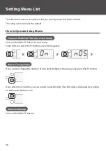
Page 22: ... F1 button to start setup Every time you press the F1 button a new item appears PASS Fail M PASS Fail M PASS Fail M How to Change Setup If you want to change the number of the selected digit or the setup value press the F3 button PASS Fail M If you press the F2 button you can move to another digit The third digit is displayed by scrolling on the screen if there is one PASS Fail M How to End Setup ...

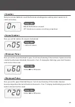
Page 23: ...ere you set the lower threshold for pass fail of screw fastening If the number of pulses becomes smaller than the lower threshold the result is Fail To display the third digit press the F2 button and scroll on the screen PASS Fail M Setup value 000 to 060 to 999 pulses Maximum Pulse Here you set the upper threshold for pass fail of screw fastening If the number of pulses becomes larger than the lo...

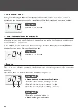
Page 24: ...n of the device longer than the set time the number of fastened screws of the last count down is to be counted up PASS Fail M Setup value 0 1 to 0 4 to 1 0 seconds System This is used to set whether or not to use the buzzer sound for button operation and to use reverse counting This has no effect on the buzzer sound of direct teaching or Fail PASS Fail M Setup value🅐 0 Buzzer is active reverse cou...

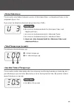
Page 25: ...An error is to be detected only for Maximum Pulse 3 An error is to be detected both for Minimum Pulse and Maximum Pulse Total Torque ups count This indicates the total torque ups PASS Fail M 🅐 1 million torque ups 🅑 0 1 million torque ups Inactive Time of Torque up This is used to set the time during which re torque up confirming fastening re fastening etc just after torque up is not to be detecte...

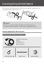
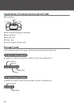
Page 26: ...ounter is set inactive no data is sent Confirm it is active before you start communication with external devices For details refer to Setting Menu List P 22 Checking Supplied the Cable Accessories BLG BC2 3010 BLG 4000BC2 BLG 5000BC2 Series Specifications of Special Cable Straight Total length 3 m D Sub 9 pin female Phone plug Ø2 5 mm Clasp to hold the cable Cable tie 10 pcs Software CD ROM ...

Page 27: ... BC2 3012 for BLG 4000BC2 LT BLG 7000BC2 Specifications of Special Cable Straight Total length 3 m D Sub 9 pin female Straight plug one touch 6 pcs Clasp to hold the cable for BLG 4000BC2 LT Cable tie 10 pcs ...

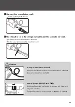
Page 28: ...ver Turn off the power before removing the cord 2Tilt the hanger 3Connect the special cable to the I O port 4Attach the clasp for holding to the connector Use the hook of the clasp to catch the cable and fit the clasp into the recess of the connector Confirm that the direction of the clasp is correct BC2 COUNT CONTROL M ...

Page 29: ...ove Fix it at a few points along the screwdriver cord Caution A Loop to Avoid Excessive Load A loop of the cable is made by a cable tie so that it has some looseness Do not fix it too tight How to Remove BLG BC2 3012 Cable Do not pull the cable too hard to disconnect it Otherwise it may cause a failure You can disconnect it by sliding the locked part of the plug BC2 COUNT CONTROL ...

Page 30: ...le so that it does not move Fix it at few points along the screwdriver cord Caution A Loop to Avoid Excessive Load A loop of the cable is made by a cable tie so that it has some looseness Do not fix it too tight How to Remove BLG BC2 3012 Cable Do not pull the cable too hard to disconnect it Otherwise it may cause a failure You can disconnect it by sliding the locked part of the plug BC2 COUNT CON...

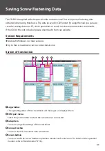
Page 31: ...our website System Requirements Microsoft Windows 7 or later versions Up to four screwdrivers can be connected at once Screen of Connection Log window The operating status of the screwdriver and messages are displayed here COM port menu Select the port number to which the screwdriver is connected Setup item You can change the settings of the screwdriver Connect button You can connect disconnect th...

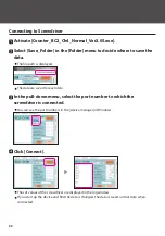
Page 32: ...played The data are saved for each date 3In the pull down menu select the port number to which the screwdriver is connected You can see the port numbers in the device manager of Windows 4Click Connect The set values of the screwdriver are displayed in the log window If you start up the device and find the date is changed the data is saved on that date when connected ...

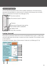
Page 33: ...t the screwdriver The number of pulses in operation Torque up The number of fastened screws and the last number of pulses at judgment Judgment result Stop of the screwdriver Sending Command If you click on an item the command is set in Set command field Enter a value a number there and click Send button the set value number is sent to the screwdriver The command is saved in the screwdriver For det...

Page 34: ...the last count down If you perform a reverse operation of the device longer than the set time the number of fastened screws of the last count down is to be counted up System This is used to set whether or not to use the buzzer sound for button operation and to use reverse counting This has no effect on the buzzer sound during direct teaching or of Fail judgment Pulse detection This is used to set ...

Page 35: ...e set number of screws to be fastened and the number already fastened are displayed Number of pulses The number of pulses from start to stop of the screwdriver is displayed Comp indicator It turns on 500 ms when the set number of screws to be fastened is reached T Up indicator It turns on 500 ms when torque up is confirmed Start On indicator It turns on when you start the screwdriver Lever Ope ind...

Page 36: ... send the setting Set button The setting is sent to the port selected in the port list How to save setting 1Click the Setting menu The connection with the screwdriver is cancelled 2Change the setting item if necessary The items are the same as those on the setting screen For the details refer to Sending Command P 33 3Select Save As in the File menu to decide where to save the data The file path fo...

Page 37: ...e list to which you want to send the change and click the Set button When transmission is completed the result is displayed in the Result space If the result is NG review the setting value In addition you cannot send the file if there is a vacant space in the setting value Finally select Exit in the File menu to close the window and connect the screwdriver again Then confirm that the setting value...

Page 38: ... Communication format ASCII Message Format The message format has two types setting command and inquiry command Format for Setting Command Example You want to change the number of screws to be fastened to 3 S n 3 n Command Delimiter Colon Data Format for Inquiry Command Example You want to review the set number of screws to be fastened Command Delimiter Q n n ...

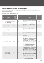
Page 39: ...ower threshold for pass fail x 1 to 999 Qc 4 Maximum pulse SC x AC x To set any upper threshold for pass fail x 1 to 999 QC 5 Work reset timer St x At x To set the length of the buzzer when the number of screws set by Screw Counter is completed and the reception time for cancellation of the final count down by reverse rotation x 00 to 39 0 0 to 3 9 seconds The response message does not contain the...

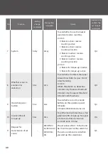
Page 40: ...detect the upper lower thresholds for pass fail of screw fastening x 0 to 3 0 Both thresholds no detection 1 Detect only the lower threshold 2 Detect only the upper threshold 3 Detect both thresholds QU 9 Operation panel button So x Ao x To set whether or not to enable buttons on the operation panel 0 Enable 1 Disable M indicator turns on Qo 10 Inactive time of torque up SG x AG x To set the inact...

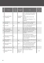
Page 41: ...perational status of the screwdriver 0 Stop of the screwdriver 1 Start of the screwdriver 16 Pulse count message Pulse nnn The number of pulses in operation n is sent with a constant interval In case over 1000 pulses is displayed 17 Torque up message T This is sent when a screw is seated 18 Message of fastening is normal D x Number of pulses This is sent when judged as PASS x the number of screws ...

Page 42: ... number of fastening being reached Over The screwdriver will be locked by this message when the total number of fastening is over one million Overhaul or maintenance is required 27 Message of unlocking after locking SL This unlocks the screwdriver temporarily after it is locked because of the total number of fastening is over one million 28 Total number of torque ups AL x You can review the total ...

Page 43: ... the torque by referring to Reference table of output torque The screwdriver does not start rotation Check if power is supplied If power is supplied and the device does not start turn off the power once and check if the cord is connected correctly Then turn on power again Check if the FOR REV switch is not at 0 The number of pulses has an error It happens when you use positive rotation just after ...

Page 44: ...t the same time This message will be displayed when the pulse exceeds 1000 after starting the screwdriver Fail M PASS The Minimum Pulse and the Maximum Pulse are wrongly placed in the reference values If you want to manually enter the number of pulses set the tolerance factor to 0 Want to See the Device Version Follow the procedure below press and hold the F1 button press the F3 button to set it O...

Page 45: ...45 We determined the guarantee period by assuming the screwdriver is used 8 hours a day We recommend periodic overhaul inspection once a year After sales services Maintenance ...

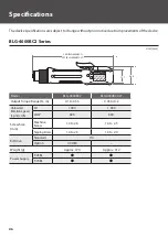
Page 46: ...G 4000BC2 207 BLG 4000BC2 LT Model BLG 4000BC2 BLG 4000BC2 LT Output Torque Range N m 0 1 to 0 55 0 03 to 0 2 Unloaded Rotation Speed r p m 10 HI 1 000 1 000 LOW 690 690 Screw Size mm Machine Screw 1 4 to 2 6 1 0 to 2 3 Tapping Screw 1 4 to 2 3 1 0 to 2 0 Bit Drive Standard H4 Option 1 4HEX Weight g Approx 370 Approx 312 Power Supply T 45BL T 70BL Specifications Unit mm ...

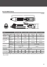
Page 47: ...eed r p m 10 HI 1 000 1 500 1 800 730 LOW 690 1 000 1 200 Screw Size mm Machine Screw 2 0 to 3 0 2 3 to 3 0 2 3 to 3 0 2 0 to 4 0 Tapping Screw 2 0 to 3 0 2 0 to 2 6 2 0 to 2 6 2 0 to 3 0 Bit Drive Standard H4 H5 and 5HEX Option H5 and 5HEX 1 4HEX 1 4HEX Weight g Approx 425 Power Supply T 45BL T 70BL Set the voltage output switch to HI for use If set to LOW the screwdriver s unique performance may...

Page 48: ...ded Rotation Speed r p m 10 HI 1 200 LOW 800 Screw Size mm Machine Screw 2 6 to 5 0 Tapping Screw 2 6 to 4 0 Bit Drive Standard H5 and 5HEX Option 1 4HEX Weight g Approx 670 Power Supply T 45BL T 70BL Set the voltage output switch to HI for use If set to LOW the screwdriver s unique performance may not be fully exhibited Unit mm ...

Page 49: ...United States and or other countries All other product and brand names are registered trademarks trademarks or service marks of their respective owners Illustrations used in this manual Illustrations used in this manual are those for BLG 4000BC2 and T 45BL unless otherwise noted However if models have differences multiple illustrations are also displayed with the model names such as BLG XXXX BLG X...

Page 50: ......

Page 51: ......

Page 52: ...HIOS Inc 1 35 1 Oshiage Sumida ku Tokyo Japan 131 0045 www hios com ...

Reviews: