background image

Communication Functions

31

You can send commands to the instrument from a PC with a program created in Visual 
Basic and take measurements. For details about the communication commands, see the 
supplied application disk (CD). The explanation of the communication commands is saved 
in the HTML format. 

Make preparations before starting communications. 

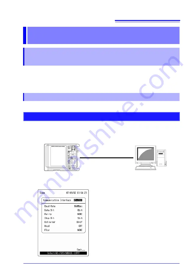
1.

Connect the PC and the instrument with the 9612 RS-232C CABLE. (

 p. 5)

2.

Set the instrument's Comm screen. (

 p. 9)

Example of Comm screen settings

Comm screen

Communication Functions

Take Measurements with Communication 


Commands

Communication Preparation

When using RS-232C

PC

Model 9612 RS-232C CABLE

(cross)

Noise HiLogger

Summary of Contents for HiLogger 3145-20

Page 1: ...Communications INSTRUCTION MANUAL For the 3145 20 NOISE HiLOGGER Explains the communication functions which can be used via the LAN and RS 232C interfaces ...

Page 2: ......

Page 3: ... Items 18 PPP RS 232C Modem Communications 23 RS 232C Cable Connection 23 PPP Settings 25 Communication Functions__________________31 Take Measurements with Communication Commands 31 Communication Preparation 31 Sending Communication Commands 34 Remote Measurement Using HTTP Server 35 Communication Preparation 35 Control with the Web Browser 38 Receiving Email when there is a Warning 45 Communicat...

Page 4: ... Data Download 62 FTP Authentication 63 FTP Server Settings ________________________ 64 PC Settings during PPP Communication___ 77 Answer Calls on the Instrument from the PC 77 Calling from the Instrument to PC 97 ...

Page 5: ...5 20 s basic measuring method for first time users 2 Instruction Manual Contains explanation and instructions regarding the instrument s operating method and functions CD Content 3 DATA VIEWER for 3145 Instruction Manual Contains information about PC soft ware which can analyze the measure ment data recorded by the instrument 4 Communications Instruction Manual this manual Explains the communicati...

Page 6: ...mation Indicates quick references for operation and remedies for troubleshooting Indicates that descriptive information is provided below Menus commands dialogs buttons in a dialog and other names on the screen and the keys are indicated in brackets Unless otherwise specified Windows represents Win dows 95 98 Me Widows NT Windows 2000 or Win dows XP Dialog box represents a Windows dialog box Click...

Page 7: ...in Visual Basic for example remote operation by a HTTP server is not possible 2 Email may not be sent depending on your Internet service provider In such case send mail via the intra network mail server using a LAN Overview Interface Communications RS 232C p 5 10BASE T LAN p 7 PPP p 23 Send communication commands from a PC to the instrument and take measurements p 31 Available Available Available ...

Page 8: ...tandard LAN Local area networks LANs are systems that provide communications between PCs in a limited areas at particular locations such as offices facto ries and schools The Ethernet 10BASE T interface provided in the instruments is a standard LAN connection interface that uses TCP IP communications protocols The 10BASE T standard is defined by IEE 802 3i as having a transfer speed of 10 Mbps Con...

Page 9: ...ications RS 232C Connection The 9612 RS 232C CABLE and the instrument connectors should be mated carefully Forcing the connectors together can damage the con tacts The RS 232C interface is not isolated from the instrument chassis Model 9612 RS 232C CABLE cross Upper Panel of theNoise HiLogger PC RS 232C port Pin No Circuit Designation CCITT EIA Symbol JIS Symbol Common 2 Receive Data Receive Data ...

Page 10: ... blinking cursor to Communication Interface and open the selection window with 4 Press and select RS 232C and set with To cancel press 5 Set each of the items continually If overrun or framing errors occur reduce the communications speed Do not attempt change settings while communications are underway RS 232 Settings Items Settings Baud Rate 1200 bps 2400 bps 4800 bps 9600 bps 19200 bps Data Bits ...

Page 11: ...surement Data from an FTP Server p 60 1 Connect the hub to the instrument s 10BASE T LAN connection terminal with the 9642 LAN CABLE 2 Connect the PC to the hub with another LAN cable 10BASE T LAN Communications LAN Connections When the instrument and a PC are connected through a hub Model 9642 LAN CABLE straight Upper Panel of theNoise HiLogger PC HUB Model 9642 LAN CABLE straight 10BASE T Ethern...

Page 12: ...AN CABLE to the cross over adapter 3 Connect the LAN cable s connector to the PC When the instrument and a PC are connected one to one Cross conversion connector Model 9642 LAN CABLE Upper Panel of theNoise HiLogger PC 10BASE T Ethernet connec tion port RJ 45 The instruments network settings must be correct in order to commu nicate with a PC via LAN When connecting to an existing LAN contact the n...

Page 13: ...ection window with 4 Press and select 10BASE T and set with To cancel press 5 Set each of the items continually LAN Connection Examples p 14 Communication Problems p 16 LAN Setting Items p 18 LAN Settings Items Settings Host Name Up to 12 characters DHCP OFF ON IP Address represents 0 to 255 Subnet Mask represents 0 to 255 Port X represents 0 to 9 Setting range 100X to 999X Gateway OFF ON represen...

Page 14: ... 35 Receiving Measurement Data from an FTP Server p 60 Items Settings FTP HTTP Authentication OFF ON User Name Up to 12 characters Password Up to 12 characters Each character is shown on the screen as an asterisk Monitor Server OFF ON Server Name Up to 32 characters IP Address represents 0 to 255 Port represents 0 to 9 Setting range 1000 to 9999 Delimiter LF CR LF Header OFF ON ...

Page 15: ...Address 1 to 3 Up to 32 characters Mail Server Up to 32 characters Mail Server IP Address represents 0 to 255 Sender Address Up to 32 characters Sender Name Up to 32 characters Subject Up to 32 characters Message Up to 32 characters Add Instanta neous Data OFF ON Send at Stop Trigger OFF ON Send at Alarm OFF ON Send at Start Backup OFF ON Send at Memory Full OFF ON Send at Card Full OFF ON ...

Page 16: ...dress Date Attach Host Name to file name to be sent Attach IP address to file name to be sent Attach time of day to file name to be sent Communication Sta tus FTP Result of FTP data transfer Total number of items Number of items sent Number of items failed to send and Number of items not yet sent Communication Sta tus Mail Result of mail transfer Total number of items Number of items sent Number o...

Page 17: ...page 5 5 with Set each of the items Receiving Email when there is a Warning p 45 Items Settings Option Setting Mail Authentication OFF ON Server Name POP Up to 32 characters IP Address POP represents 0 to 255 Account Name Up to 32 characters Password Up to 32 characters ...

Page 18: ...ly but there is no problem with using a pri vate IP address Set the instrument as shown below so that every instrument has a unique host name and IP address LAN Connection Examples Connecting one PC and one instrument with a 9642 LAN CABLE PC Settings IP Address 192 168 1 1 Subnet Mask 255 255 255 0 The network settings on the PC are made in the Network dialog box To get to this dialog box double ...

Page 19: ... below so that every instrument has a unique host name and IP address Connecting one PC to multiple instrument s in a HUB The first instrument The settings are made manually Items Settings Host Name LOGGER1 IP Address 192 168 1 2 The second instrument The settings are made manually Items Settings Host Name LOGGER2 IP Address 192 168 1 3 The third instrument The settings are made manually Items Set...

Page 20: ...plied with the 9642 LAN CABLE is a cross cable The connector is a straight male female converter The cable might not be connected to the connector properly Remove the cable and then connect it again Choose Run from the Start menu Type winipcfg Windows95 98 Me or ifconfig all Windows NT 2000 XP and click Enter Doing so will enable you to get the IP address of the PC s network interface subnet mask ...

Page 21: ...192 168 1 2 and press Enter If the screen display is as shown below the instrument and the PC are communicating properly Time represents how long it took for the instrument and the PC to communi cate Pinging 192 168 1 2 with 32 bytes of data Reply from 192 168 1 2 bytes 32 time 10ms TTL 32 Reply from 192 168 1 2 bytes 32 time 10ms TTL 32 Reply from 192 168 1 2 bytes 32 time 10ms TTL 32 Reply from ...

Page 22: ...Subnet Mask 1 ___ ___ ___ ___ Port No When the default 8800 8809 cannot be used Specify the first three of four decimalcolumns and 0 to 9 in the first col umn is used and reserved by this machine ___X Gateway 2 yes or no Gateway IP addresses There is a Gateway 2 ___ ___ ___ ___ DNS server 3 yes or no DNS server IP address There is a DNS server 3 ___ ___ ___ ___ 1 Skip setting if you use DHCP 2 Ski...

Page 23: ...ther network settings will be automati cally assigned to the instruments The Obtain an IP address automatically option in TCP IP IP Address of Network dialog box in Windows 95 98 Me 2000 uses DHCP The TCP IP protocol used by this instrument for LAN communications uses IP addresses to identify each instrument Version 4 IPv4 standard IP addresses consist of 32 bit numerical values normally indicated...

Page 24: ...host address are set to 0 For example if the first 24 bits show the network address and the remaining 8 bits show the host address the network will be shown as follows 11111111 11111111 11111111 00000000 This is represented by a hexadecimal number 0xffffff00 or as with an IP address by a number with decimals 255 255 255 0 When a net mask is combined with an IP address it is shown as 192 168 1 1 24...

Page 25: ...howing the subnetwork If all the bits of the host address are 1 the address will be used as a broadcast address showing all the hosts on the subnet work In these cases the address cannot be used as the IP address of the instrument For example if the network is 192 168 1 0 24 the address 192 168 1 255 shows all the instruments connected to the subnet of 192 168 1 0 On this subnet you can use a tota...

Page 26: ...y the IP address The addresses consist of a series of numbers and they are not easy to remember To simplify a text based host name is used instead of an IP address On a network host names and IP addresses have to be converted from one to the other There are two systems to perform such conversion DNS and WINS This instrument uses the DNS system When DNS is on a network with DNS turned ON and the IP...

Page 27: ...asurement Data from an FTP Server p 60 1 Connect the 9721 RS 232C CABLE to the instrument s RS 232C connection ter minal 2 Connect the 9642 LAN CABLE s connector to the modem 3 Connect the modem to the PC with the RS 232C cable You can also use USB cable or a PC card PPP RS 232C Modem Communications RS 232C Cable Connection Public switched network modem Modem Modem Model 9721 RS 232C CABLE straigh...

Page 28: ...When using a modem connected to a private branch exchange PBX or TA you may not be able to hear the dial tone i e sound you hear after picking up the telephone receiver In that case suffix X3 to the AT command When making a call from an extension to an outside line or to dial a number after dialing 0 enter 0 zero and a comma before the tele phone number as in 0 This keeps the phone waiting a certa...

Page 29: ...ations 1 Press and open the Status screen and move the blinking cursor to Comm with 2 Press and open the Comm screen 3 Press and move the blinking cursor to Communication Interface and open the selection window with 4 Press and select PPP and set with To cancel press PPP Settings ...

Page 30: ... to 32 characters DNS OFF ON IP Address represents 0 to 255 Mail Dial Number 0123456789 Connect Account Up to 32 characters Connect Password Up to 32 characters DNS OFF ON IP Address No 1 represents 0 to 255 IP Address No 2 represents 0 to 255 Retry Count represents 0 to 9 Setting range 0 to 10 times Retry Interval represents 0 to 9 Setting range 0 to 10 minutes Host Name Up to 12 characters Curre...

Page 31: ...ransmission speed to 19200 bps Items Settings Receipt Account Up to 12 characters Receipt Password Up to 12 characters Disconnect Timeout represents 0 to 9 Setting range 0 to 10 minutes FTP HTTP Authentication OFF ON User Name Up to 12 characters Password Up to 12 characters AT Command Up to 20 characters Baud Rate 1200 bps 2400 bps 4800 bps 9600 bps 19200 bps Delimiter CR LF CR Header OFF ON Port...

Page 32: ...racters Mail Server Telephone IP address and server name Mail Server Name Up to 12 characters Mail Server IP Address represents 0 to 255 Sender Address Up to 32 characters Sender Name Up to 32 characters Subject Up to 32 characters Message Up to 32 characters Add Instanta neous Data OFF ON Send at Stop Trigger OFF ON Send at Alarm OFF ON Send at Start Backup OFF ON Send at Memory Full OFF ON Send ...

Page 33: ...o File Name Host Name IP Address Time Attach host name to file name to be sent Attach IP address to file name to be sent Attach time of day to file name to be sent Communication Status FTP Result of FTP data transfer Total number of items Number of items sent Number of items failed to send and Number of items not yet sent Communication Status Mail Result of mail transfer Total number of items Numb...

Page 34: ... 5 5 with Set each of the items Receiving Email when there is a Warning p 45 Items Settings Option Setting Mail Authentication OFF ON Server Name POP Up to 32 characters Server IP Address POP represents 0 to 255 Account Name Up to 32 characters Password Up to 32 characters ...

Page 35: ...anation of the communication commands is saved in the HTML format Make preparations before starting communications 1 Connect the PC and the instrument with the 9612 RS 232C CABLE p 5 2 Set the instrument s Comm screen p 9 Example of Comm screen settings Comm screen Communication Functions Take Measurements with Communication Commands Communication Preparation When using RS 232C PC Model 9612 RS 23...

Page 36: ...C and the instrument with the 9642 LAN CABLE p 7 2 Set the instrument s Comm screen p 9 Example of Comm screen settings Comm screen 10BASE T 1 5 When using 10BASE T LAN PC Model 9642 LAN CABLE straight Cross conversion connector Noise HiLogger ...

Page 37: ... 232C cable You can also use USB cable or a PC card 3 Set the instrument s Comm screen p 25 4 Set communications on the PC p 77 Example of Comm screen settings Comm screen 10BASE T 2 5 When using PPP Public switched network modem Modem Modem Model 9721 RS 232C CABLE straight Straight cable included with modem USB RS 232C or PC Card RS 232C ...

Page 38: ... the CD ROM drive 2 The main screen will open automatically Click English for the display lan guage If the main screen does not open automatically open index htm with a web browser 3 Click Communication Commands Manual 4 The communication commands manual will open 5 Create a program and execute it Sending Communication Commands ...

Page 39: ...n start and stop measurements display the current measurement value retrieve the internal memory data retrieve data via FTP set comments and perform remote control Make preparations before starting communications 1 Connect the PC and the instrument with the 9642 LAN CABLE p 7 2 Set the instrument s Comm screen p 9 Example of Comm screen settings Comm screen 10BASE T 1 5 2 5 Remote Measurement Usin...

Page 40: ... can also use USB cable or a PC card 3 Set the instrument s Comm screen p 25 4 Set the modem on the PC Consult the instruction manual supplied with each modem 5 Set the dial up settings on the PC p 77 When using PPP Modem Modem Model 9721 RS 232C CABLE straight Straight cable included with modem USB RS 232C or PC Card RS 232C Public switched network modem ...

Page 41: ...Refer to Answer Calls on the Instrument from the PC p 77 Disconnect Timeout When no communication is performed the instrument waits the time set here before disconnecting AT Command If necessary the AT command can be specified for the modem as an option Refer to PPP RS 232C Modem Communications p 23 Commands Consult the instruction manual supplied with each modem Port Delimiter Header Specify the ...

Page 42: ...yed Enter http 192 168 1 2 here 3 Click SETTING PAGE When connected via a modem using PPP communications the address is like http 192 168 55 2 4 If FTP HTTP Authentication is ON on the instrument s Comm screen you are asked for your user name and password Enter your user name and password and click Set 5 The instrument s screen will be displayed in the web browser as is Control with the Web Browse...

Page 43: ...nd remove the check from the box for Use a proxy server if it is checked If the HTTP screen appears but the remote control screen does not Choose Tools Internet Options on the Internet Explorer tool bar and click on the Security tab Choose Internet and click on the Customize Level but ton Scroll down to Java permissions and choose a permission level to enable Java If Java is not installed reinstal...

Page 44: ... the settings screen The screen below will be dis played 2 Click START The instrument s logging measurement will start You can check the current measurement status on the browser 3 Click STOP to stop the measurements Starting and stopping measurement ...

Page 45: ...Communication Functions 41 1 Click CURRENT DATA DISP on the settings screen The screen below will be displayed 2 To change the screen s renewal rate set with DATA RENEWAL TIME Current value display ...

Page 46: ...al memory during the instrument measurement You can also retrieve all of the data Click 3145 FORM DATA to retrieve binary data click Get Text to retrieve text data Acquiring data from memory If you cannot save data by clicking on 3145 FORM DATA right click 3145 FORM DATA and from the menu execute Save Target As If you cannot save the text data perform in the same way ...

Page 47: ...our user name and password Enter your user name and pass word and click Set See also Receiving Measurement Data from an FTP Server p 60 Data acquisition using FTP During measurements you cannot retrieve measurement data in inter nal memory You can retrieve them after stopping measurement We recommend that you set the user name and password on the instrument s Comm screen to restrict connections to...

Page 48: ...Communication Functions 44 1 Click COMMENT SET on the settings screen The screen below will be dis played 2 Set the instrument s comments Comment settings ...

Page 49: ...PC and the instrument with the 9642 LAN CABLE p 7 2 Set the instrument s Comm screen p 9 Receiving Email when there is a Warning If warnings are frequently generated you may receive not a few emails In order to avoid this set warning retention to ON on the set tings screen so that you can receive only the first warning for each warning channel Email can be sent during logging measurements only Dur...

Page 50: ...en 10BASE T 1 5 Comm screen 10BASE T 3 5 IP address 192 168 1 2 Send Mail To 1 ON Address 1 abc xyz xx xx Send Mail To 2 OFF Address 2 Send Mail To 3 OFF Address 3 Mail Server IP Address 192 168 1 100 Set the SMTP mail server Sender Address logger xyz xx xx Sender Name logger Subject logger_mail Message Mail from logger Timing ON Stop Trigger OFF Alarm OFF Start Backup OFF Memory Full OFF Card Ful...

Page 51: ...il is connected or the telephone number on the PC side Connect Account Set the user name of the Internet service provider or user name e g logger to be entered in the PC s remote access server i e Incoming Connections dial up server Refer to Answer Calls on the Instrument from the PC p 77 Connect Password Set the password of the Internet service provider or password e g logger to be entered in the...

Page 52: ...dem as an option Refer to PPP Settings p 25 See the Instruction Manual of your modem Baud Rate Slow down if you cannot communicate Comm screen PPP 3 5 When the DNS is enabled use the specified IP address other than 0 0 0 0 If the specified IP address is 0 0 0 0 use the IP address obtained by referring to the DNS by its server name At that time specify the server name in full domain as server xyz x...

Page 53: ...Communication Functions 49 Start the instrument s measurements In the warning state you will receive an email via the mail server Example of received email Receiving Warning Email ...

Page 54: ...ons to send the interrupted and remaining to be sent mail Comm screen 4 5 Executing the mail transfer test sends test mail If the test mail cannot be sent check whether the settings you made are correct The mail transfer time required when sending mail via PPP at 9600 bps is about 100 bytes 8 bits 9600 bps just under one second Moreover additional time is required before and after sending mail abo...

Page 55: ... from the SMTP server When POP before SMTP is used set up mail authentication POP as shown below 1 Choose ON in mail authentication POP 2 Specify the server name POP or IP address POP as below Server name Specify the receiving server POP server using the host name DNS is necessary IP address Specify the receiving server POP server using the IP Account name Mail account name of the receiving server...

Page 56: ...reen To regularly save send data set the save mode to Inter val or Ref Time If you want to continue saving sending data even when the PC card becomes full set the save mode to Delete For details refer to the instruction manual FTP Server You can use Windows FTP server For the FTP server set the user name and password for the instrument and register it For details see the Windows FTP server help Yo...

Page 57: ...screen p 9 4 Set automatic saving on the instrument Check if a PC card has been inserted For details refer to the instruction manual Example of Comm screen settings When sending data to FTP server 192 168 1 1 Comm screen 10BASE T 1 5 Communication Preparation When using 10BASE T LAN Model 9642 LAN CABLE Noise HiLogger e g 192 168 1 2 FTP server PC e g 192 168 1 1 Host Name LOGGER IP Address 192 16...

Page 58: ...his helps to identify a specific instrument FTP Auto Transfer ON FTP Server IP Address 192 168 1 1 Set the PC on which the FTP server operates User Name logger User name of this instru ment registered in FTP server on PC side Password logger Password of this instru ment registered in FTP server on PC side Append Identifier to File Name Host Name Attach host name to file name to be sent Set on Comm...

Page 59: ...ction manual supplied with each modem 4 Set the FTP server on the PC p 64 5 Set the remote access server on the PC p 97 6 Set the instrument s Comm screen p 25 7 Set automatic saving on the instrument Check if a PC card has been inserted For details refer to the instruction manual When using PPP Modem Modem Model 9721 RS 232C CABLE straight Straight cable included with modem USB RS 232C or PC Card...

Page 60: ...e and FTP server IP address as shown below Other settings are the same as when communicating via a LAN Specify the PC on which the FTP server oper ates To send to the PC normally set Telephone Telephone Specify the PC at the Telephone IP Address Specify the server by IP Server Name Specify the server by host name DNS is required ...

Page 61: ... of DNS To use the DNS at the connected destination set the IP address of the DNS Retry Count Retry Interval If the call cannot be connected the number is redialed after waiting the specified retry interval as many times as specified by the retry count AT Command If necessary the AT command can be specified for the modem as an option See PPP Settings p 25 Command See the Instruction Manual of your...

Page 62: ...ion status FTP To 10 Fi 7 Mi 1 Ye 2 Among the ten items of FTP data seven have already been sent one could not be sent and two have yet to be sent because transfer is cur rently underway St 2 indicated instead of Ye 2 means that two items have not been sent because transfer was interrupted by the button Wa 2 indicated instead of Ye 2 means that there are two items remaining to be sent and awaiting...

Page 63: ... side into account however the actual transfer time is a little 2 minutes Moreover additional time is required before and after data transfer about 30 seconds to make a call and about 30 sec onds to disconnect The transfer time via LAN is 90K bytes 8 bits 10 Mbps 0 1 second When taking the time needed to create data on the main instrument side into account however the actual transfer time is a lit...

Page 64: ...ment and PC card files into the PC using the FTP client running on the PC 1 Connect the PC and the instrument with the 9642 LAN CABLE p 7 2 Set the instrument s Comm screen p 9 Comm screen 10BASE T 2 5 1 5 Receiving Measurement Data from an FTP Server Communication Preparation When using 10BASE T LAN Model 9642 LAN CABLE Noise HiLogger e g 192 168 1 2 PC ÅiInternet ExplorerÅj e g 192 168 1 1 ...

Page 65: ... a PC card 3 Set the modem on the PC Consult the instruction manual supplied with each modem 4 Set the dial up settings on the PC p 77 5 Set the instrument s Comm screen p 25 Example of Comm screen settings Comm screen PPP 2 5 When using PPP Modem Modem Model 9721 RS 232C CABLE straight Straight cable included with modem USB RS 232C or PC Card RS 232C Public switched network modem ...

Page 66: ...55 2 during PPP communication The screen below will be displayed 3 Copy the measurement data in the MEMORY folder If there is SETUP SET and measurement data there are MEMORY MEM and MEM ORY TXT files and they can be downloaded to the PC 4 Copy the data in the CARD folder By downloading the files in the MEMORY directory you can retrieve the instrument s mea surement data and setting data in file fo...

Page 67: ...les during real time save automatic save manual save file delete directory create delete name edit or format operations If data is being written to the PC card using the FTP at the start of automatic saving or calculation data saving FTP operation will be interrupted to save data If the instrument ends measurement during data transmission using the FTP transmission may be interrupted to save data ...

Page 68: ...ndows XP Home Edition does not include an FTP server use the free software War FTP Daemon or other third party software instead FTP Service Setup 1 On Control Panel on the Windows start menu double click Add Remove Pro grams 2 Choose Add Remove Windows Components FTP Server Settings WindowsXP Professional Double click Click ...

Page 69: ...FTP Server Settings 65 3 Choose Internet Information Services IIS then Details 4 Select the File Transfer Protocol FTP Service check box and click OK 2 Click 1 Check 2 Click 1 Check ...

Page 70: ...FTP Server Settings 66 5 Click Next You will be asked for the Windows XP CD 6 Click Finish 7 A directory named InetPub is created when installation is completed Click Click ...

Page 71: ...ettings 67 FTP Site Settings 1 Choose Administrative Tools in Control Panel 2 Choose Internet Information Services 3 Choose Default FTP Site and right click to select Property Double click Double click Right click ...

Page 72: ...FTP Server Settings 68 4 Select All Unassigned for IP Address 5 Select the Read Write and Log visits check boxes for Home Directory then click OK Select 2 Click 1 Check ...

Page 73: ...gement in Administrative Tools 2 Choose Users in Local User and Group and right click to select New User 3 Enter User name Full name Password and Password reentry for confirmation e g logger and then choose Create Double click 2 Click 1 Right click 1 Input 2 Click ...

Page 74: ...etup on Windows is complete with the above steps 5 Execute the FTP data transfer test from this instrument 192 168 1 2 to the PC 192 168 1 1 using the logger user name and logger password 6 The test file e g LOGGER_192 168 1 2_000101 055537_FTP_TEST TXT is then sent to C Intpub ftproot ...

Page 75: ...FTP Server Settings 71 FTP Service Setup 1 On Control Panel on the Windows start menu double click Add Remove Pro grams 2 Choose Add Remove Windows Components Windows2000 Double click Click ...

Page 76: ...FTP Server Settings 72 3 Choose Internet Information Services IIS then Details 4 Select the File Transfer Protocol FTP Server check box and click OK 2 Click 1 Check 2 Click 1 Check ...

Page 77: ...FTP Server Settings 73 5 Click Next 6 Click Finish 7 A directory named InetPub is created when installation is completed Click Click ...

Page 78: ...ge 2 Choose Default FTP Site for Service and Applications Internet Information Services then right click to select Property 3 Select All Unassigned for IP Address 4 Select the Read Write and Log visits check boxes for Home Directory then click OK Right click Right click Select 1 Check 2 Click ...

Page 79: ...er Registration 1 Choose Users in Local User and Group and right click to select New User 2 Enter User name Full name Password and Password reentry for confirmation e g logger and then choose Create Right click 1 Input 2 Click ...

Page 80: ...etup on Windows is complete with the above steps 4 Execute the FTP data transfer test from this instrument 192 168 1 2 to the PC 192 168 1 1 using the logger user name and logger password 5 The test file e g LOGGER_192 168 1 2_000101 055537_FTP_TEST TXT is then sent to C Intpub ftproot ...

Page 81: ...number from the PC to this instrument make sure that dial up connections have been set up on the PC side Dial Up Networking is included with Windows so refer to Windows HELP For details on how to add a modem to Windows refer to the user s manual supplied with your modem Create a New Network 1 On Control Panel on the Windows start menu double click Network Connec tions PC Settings during PPP Commun...

Page 82: ...PC Settings during PPP Communication 78 2 Choose File New Connection 3 Click Next Click Click ...

Page 83: ...PC Settings during PPP Communication 79 4 Select Connect to the Internet and click Next 5 Select Set up my connection manually and click Next 2 Click 1 Click 2 Click 1 Click ...

Page 84: ...PC Settings during PPP Communication 80 6 Select Connect using a dial up modem and click Next 7 Set the ISP Name e g LOGGER and click Next 2 Click 1 Click 2 Click 1 Input ...

Page 85: ...Next 9 Set the telephone Phone number and and click Next 10 Set the user name e g logger and password e g logger then click Next Same as receiving user name Receipt Account and password Receipt Password on this instrument side when using HTTP or FTP servers 2 Click 1 Input 2 Click 1 Input ...

Page 86: ...PC Settings during PPP Communication 82 11 Click Finish Click ...

Page 87: ... Network Settings 1 Select the connection you ve just created from Network Connections and right click to select Property 2 Click the Networking tab choose PPP Windows 95 98 NT4 2000 Internet and click on Settings Right click 2 Click 1 ëIëš ...

Page 88: ...PC Settings during PPP Communication 84 3 Deselect all check boxes for PPP Settings and click OK 4 Select Internet Protocol TCP IP then Properties 2 Click 1 Deselect 2 Click 1 Check ...

Page 89: ...PC Settings during PPP Communication 85 5 Select Obtain an IP address automatically and Obtain DNS server address automatically then click OK 6 Click OK 3 Click 1 Click 2 Click Click ...

Page 90: ...k the connection you have just created 2 Enter User name and Password e g logger and then enter the telephone number in the Dial field Click on the Dial and the dial up process will begin Use the same user name Receipt Account and password Receipt Password as on the HTTP server FTP server Double click 3 Click 1 Input 2 Input ...

Page 91: ...munication 87 Create a New Network 1 Go to Control Panel Network and Dial up Connections and double click the connection you have just created 2 Choose Make New Connection 3 Click Next Windows2000 Double click Double click Click ...

Page 92: ... Communication 88 4 Select Dial up to the Internet and click Next 5 Select I want to set up my Internet connection manually or I want to connect through a local area network LAN and click Next 2 Click 1 Click 2 Click 1 Click ...

Page 93: ...PC Settings during PPP Communication 89 6 Select I connect through a phone line and a modem and click Next 7 Set the telephone number and click Next 2 Click 1 Click 2 Click 1 Input ...

Page 94: ...nd password e g logger then click Next Same as receiving user name Receipt Account and password Receipt Password on this instrument side when using HTTP or FTP servers 9 Set the connection name e g LOGGER and click Next 10 Click Finish 2 Click 1 Input 2 Click 1 Input Click ...

Page 95: ...connection you ve just created from Network and Dial up Connec tion and right click to select Property 2 Select PPP Windows95 98 NT4 2000 Internet in Networking then Settings 3 Deselect all check boxes for PPP Settings and click OK Click 2 Click 1 ëIëš 1 Deselect 2 Click ...

Page 96: ...Communication 92 4 Select Internet Protocol TCP IP then Properties 5 Select Obtain an IP address automatically and Obtain DNS server address automatically then click OK 6 Click OK 2 Click 1 Check 3 Click 1 Click 2 Click Click ...

Page 97: ... the connection you have just created 2 Enter the user name e g logger password e g logger and telephone num ber Then select the connection to make a dial up connection Same as receiving user name Receipt Account and password Receipt Password on this instrument side when using HTTP or FTP servers Double click 2 Click 1 Input ...

Page 98: ... Networking then Make New Connection 2 Set the telephone number and click Next 3 Set the name and click Finish 4 From Dial Up Networking select the connection you ve just created and right click to select Property Windows98 WindowsMe Double click 1 Input 2 Click 2 Click 1 Input Right click ...

Page 99: ...s from all Advanced options boxes In the Allowed network protocols boxes only check the box for TCP IP then click the TCP IP Settings 6 Select the Server assigned IP address and Server assigned name server address check boxes then select the Use default gateway on remote net work check box and click OK 1 Select 2 Deselect 4 Click 3 Check 1 Click 4 Click 3 Check 2 Click ...

Page 100: ...he connection you ve just created 2 Enter the user name e g logger password e g logger and telephone num ber Then select Connect to make a dial up connection Same as receiving user name Receipt Account and password Receipt Password on this instrument side when using HTTP or FTP servers Double click 1 Input 2 Click ...

Page 101: ... instrument When dialing a number from this instrument to the PC the remote access server dial up server must be up and running before the call can be terminated on the PC side The remote access server is included with Windows so refer to Windows HELP For PPP in this instrument unsigned PAP is used for authentication Incoming Connection Settings Remote Access Server 1 Go to Control Panel Network C...

Page 102: ...PC Settings during PPP Communication 98 3 Select Set up an advanced connection and click Next 4 Select Accept incoming connections and click Next 1 Click 2 Click 1 Click 2 Click ...

Page 103: ...PC Settings during PPP Communication 99 5 Select the modem set up in your PC and click Next 6 Select Do not allow virtual private connections and click Next 1 Check 2 Click 2 Click 1 Click ...

Page 104: ...r name e g logger full name e g logger and password e g logger Confirm the password by entering logger for example then click OK Connect Password on this instrument side when sending FTP data 9 Select the logger added and click Next Click 1 Input 2 Click 1 Check 2 Click ...

Page 105: ...ngs during PPP Communication 101 10 Select Internet Protocol RCP IP and then Properties 11 Select Allow callers to access my local area network and click OK 12 Click Finish 1 Check 2 Click 2 Click 1 Check Click ...

Page 106: ...gs during PPP Communication 102 Incoming Connection Settings Remote Access Server 1 Go to Control Panel Network and Dial up Connections and choose Make New Connection 2 Click Next Windows2000 Double click Click ...

Page 107: ...PC Settings during PPP Communication 103 3 Select Accept incoming connections and click Next 4 Select the modem set up in your PC and click Next 2 Click 1 Click 2 Click 1 Check ...

Page 108: ...PC Settings during PPP Communication 104 5 Select Do not allow virtual private connections and click Next 6 Select Add 2 Click 1 Click Click ...

Page 109: ...firm the password by entering logger for example then click OK Same as calling user name Connect Account and password Connect Password on this instrument side when sending FTP data 8 Select the logger added and click Next 9 Select Internet Protocol RCP IP and then Properties 1 Input 2 Click 2 Click 1 Check 2 Click 1 Check ...

Page 110: ...g PPP Communication 106 10 Select the Allow callers access my local area network check box then click OK 11 Set Incoming Connections for the The connection will be named and click Finish 2 Click 1 Check 2 Click 1 Input ...

Page 111: ... your PC and select Allow caller access and Change Password If no choices for changing the password are available here first limit shared level access as described later 3 Enter a password in the New password and Confirm new password areas e g logger Click OK Leave Old password blank Use the same username Connect Account and password Connect Password as the con nect account and password of the ins...

Page 112: ...tab 5 Set the Type of Dial Up Server to PPP Internet Windows NT Server Win dows 98 Remove the checkmarks from all Advanced options boxes then click OK 6 Click the Apply Status will change to Monitoring 7 When a call is received Status will change to Connected 1 Select 3 Click 2 Deselect Click ...

Page 113: ...the Windows 98 Me CD and insert it in the CD drive Leave it inserted 2 My Computer Control Panel select Add Remove Programs 3 Click the Windows Setup tab Check the box for Communications and click the Detail 4 Select Dial Up Server and click OK Double click 2 Click 1 Check Check ...

Page 114: ...he Configuration tab then the File and Print Sharing 3 Check the boxes for I want to be able to give others access to my files and I want to be able to give others access to my printer then click OK 4 Click the Access Control tab Check the radio button for Share level access control and click OK Right click Click 2 Click 1 Check 2 Click 1 Click ...

Page 115: ...ki com Printed in Japan 3145A987 00 All reasonable care has been taken in the production of this manual but if you find any points which are unclear or in error please contact your supplier or the International Sales and Marketing Department at HIOKI headquarters In the interests of product development the contents of this manual are subject to revision without prior notice The content of this man...

Page 116: ...192 Japan TEL 81 268 28 0562 FAX 81 268 28 0568 E mail os com hioki co jp URL http www hioki com HIOKI USA CORPORATION 6 Corporate Drive Cranbury NJ 08512 USA TEL 1 609 409 9109 FAX 1 609 409 9108 3145A987 00 07 07H Printed on recycled paper ...

Reviews: