


INSTALLATION AND OPERATING INSTRUCTIONS
72-0112 03-06-18
7013500 314 SKLT 69 A
Page 13
SECTION 7: TREND CONTROL (1601-31 or 1601-31-1) OPERATION, Continued
Version
1
2
3
4
5
6
7
8
9
10
1 hour
6 min
12 min
18 min
24 min
30 min
36 min
42 min
48 min
54 min
60 min
24 hour
2 hr
4 hr
6 hr
8 hr
10 hr
12 hr
14 hr
16 hr
18 hr
24 hr
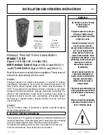
LED
A. - On/Off Light Switch
B. - Indicators - lighting, door
switch (n/a), timer and the heater
C. - On/Off Sauna Switch and fault
alarms
D. - Sets the desired value
E. - Functions - Temperature, Delay
Timer, Sauna Length and Humidity
(n/a)
F. - Function Select Buttons
CONTROL OPERATION:
TURN ON LIGHT: Press the "light bulb" icon once to turn on the light and press again to turn off. (Usage of light control is
optional)
SAUNA LENGTH: (Control 1601-31) Select the sauna length function by pressing the buttons < > (F). Set the desired usage
time (0–60 minutes) using the – and + buttons. (Setting 10 equals 60 minutes)
(Control 1601-31-1) Usage time is 0 - 24 hours operation
(Setting 1 = 2 hours, setting 10 = 24 hours)
A. B. C.
D.
E.
F.