


F20
3 Product Description
HI 800 143 E Rev. 1.01
Page 15 of 56
For more information on how to configure line control in the user program, refer to the
HIMatrix Engineering Manual (HI 800 101 E).
3.1.2
Safety-Related Digital Outputs
The controller is equipped with 8 channels, which can be individually configured as digital
input or digital output.
To configure a digital channel as an output in SILworX, use the
Channel
[BOOL] ->
system
parameter, to configure it in ELOP II Factory, use the
DO[xx].Used
system signal.
The digital channel can only be used as an output, if the value of the corresponding system
variable is set to TRUE. The variable of the respective input displays the current output
state.
At the maximum ambient temperature, the outputs 1...3 and 5...7 can be loaded with 0.5 A
each; and outputs 4 and 8 can be loaded with 1 A or with 2 A at an ambient temperature of
up to 50 °C.
If an overload occurs, one or all outputs are switched off. If the overload is removed, the
outputs are switched on again automatically, see Table 21.
A short-circuit detected on the output is signaled. The external output line, however, is not
monitored.
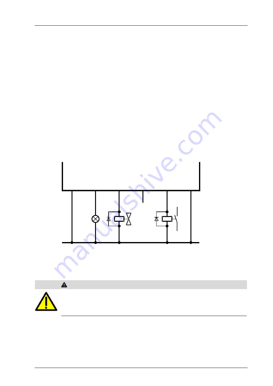
DO1
L-
DO1
DO1
DO1
L-
Figure 3:
Connection of Actuators to Outputs
The redundant connection of two outputs must be decoupled with diodes.
WARNING
For connecting a load to a 1-pole switching output, use the corresponding L- ground
of the respective channel group (2-pole connection) to ensure that the internal
protective circuit can function.
Inductive loads may be connected with no free-wheeling diode on the actuator. However,
HIMA strongly recommends connecting a protective diode directly to the actuator.


