


7.10 Working with the target plate
The target plate improves laser beam visibility. The target
plate should be used in bright conditions or whenever
improved laser beam visibility is desired. Simply bring the
target plate into the plane of the projected laser beam.
The target plate is made from a material that makes the
laser beam more easily visible.
8 Care and maintenance
8.1 Cleaning and drying
1. Blow dust off the lenses.
2. Do not touch the glass with the fingers.
3. Use only a clean, soft cloth for cleaning. If necessary,
moisten the cloth slightly with pure alcohol or a little
water.
NOTE
Abrasive cleaning materials may scratch the
glass and impair the accuracy of the laser tool.
NOTE
Do not use any other liquids as these may
damage the plastic components.
4. Observe the temperature limits when storing your
equipment. This is particularly important in winter
/ summer if the equipment is kept inside a motor
vehicle (-30°C to +60°C / -22°F to +144°F).
8.2 Storage
Remove the appliance from its case if it has become wet.
The appliance, its carrying case and accessories should
be cleaned and dried (at maximum 40°C (104°F)). Repack
the equipment only once it is completely dry.
Check the accuracy of the equipment before it is used
after a long period of storage or transportation.
Remove the batteries from the tool. Leaking batteries
may damage the tool.
8.3 Transport
Use the Hilti toolbox or packaging of equivalent quality
for transporting or shipping your equipment.
CAUTION
Remove the batteries from the tool before transport-
ing or shipping it.
8.4 Hilti Calibration Service
We recommend that the tool is checked by the Hilti
Calibration Service at regular intervals in order to ver-
ify its reliability in accordance with standards and legal
requirements.
Use can be made of the Hilti Calibration Service at any
time, but checking at least once a year is recommended.
The Calibration Service provides confirmation that the
tool is in conformance, on the day it is tested, with the
specifications given in the operating instructions.
The tool will be readjusted if deviations from the man-
ufacturer’s specification are found. After checking and
adjustment, a calibration sticker applied to the tool and
a calibration certificate provide written verification that
the tool operates in accordance with the manufacturer’s
specification.
Calibration certificates are always required by companies
certified according to ISO 900x.
Your local Hilti Center or representative will be pleased
to provide further information.
8.4.1 Checking accuracy
In order to ensure compliance with the technical speci-
fications, the tool should be checked regularly (at least
before each major / relevant job).
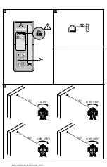
8.4.1.1 Checking the main and transverse
horizontal axes
17
1. Set up the tripod approx. 20 m (60 ft) from a wall
and adjust the tripod head horizontally with a spirit
level.
2. Mount the tool on the tripod and use the aiming
notch to aim the tool at the wall.
3. Use the receiver to catch the laser beam and mark
a point (point 1) on the wall.
4. Pivot the tool clockwise through 90° about its own
axis. In doing so, ensure that the height of the tool
does not change.
5. Use the laser receiver to catch the laser beam and
mark a second point (point 2) on the wall.
6. Repeat steps 4 and 5 twice and mark points 3 and
4 on the wall with the aid of the laser receiver.
When this is done carefully, the vertical distance
between the two marked points, i.e. points 1 and 3
(main axis) or points 2 and 4 (transverse axis) should
be < 5 mm (at 20 m) (¹/₈" at 60 ft) in each case. If
the deviation is greater than this, the tool should be
returned to a Hilti Service Center for calibration.
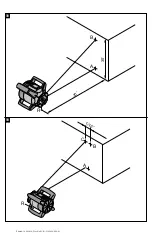
8.4.1.2 Checking the vertical axis
18 19
1. Set up the tool in the vertical position on the floor
or flat ground at a distance of approx. 10 m (30 ft)
from a wall.
2. Adjust the position of the tool so that the grips are
parallel to the wall.
3. Switch the tool on and mark the reference point (R)
on the floor.
4. With the aid of the receiver, mark point (A) at the
base of the wall (set the rotating laser to medium
speed).
5. With the aid of the receiver, mark point (B) at a
height of approx. 10 m (30 ft).
6. Pivot the tool through 180° and realign it with the
reference point (R) on the floor and with point (A) at
the base of the wall.
7. With the aid of the receiver, mark point (C) at a
height of approx. 10 m (30 ft).
NOTE
When this is done carefully, the horizontal
distance between the two points (B) and (C) marked
at a height of 10 meters (30 ft) should be less than
1.5 mm (at 10 m) (¹/₁₆" at approx. 30 ft). If the
deviation is greater: Please return the tool to a Hilti
Service Center for calibration.
en
13
Printed: 14.04.2014 | Doc-Nr: PUB / 5162040 / 000 / 01
Summary of Contents for PRI 36
Page 2: ...1 Printed 14 04 2014 Doc Nr PUB 5162040 000 01...
Page 3: ...2 3 4 5 Printed 14 04 2014 Doc Nr PUB 5162040 000 01...
Page 4: ...6 7 8 9 10 11 Printed 14 04 2014 Doc Nr PUB 5162040 000 01...
Page 5: ...12 14 13 Printed 14 04 2014 Doc Nr PUB 5162040 000 01...
Page 6: ...35 15 D F E G 17 16 Printed 14 04 2014 Doc Nr PUB 5162040 000 01...
Page 7: ...18 5 19 5 Printed 14 04 2014 Doc Nr PUB 5162040 000 01...


