


7.6.1 Setting up
NOTE
The slope can be set manually, automatically, or by using
the PRA 76/78 slope adapter.
1. Set up the rotating laser in a suitable position for the
application, e.g. on a tripod.
2. Position the rotating laser and tripod either at the
upper edge or lower edge of the inclined plane. If the
rotating laser is positioned at the upper edge of the
inclined plane, check that the control panel on the
PRI 36 faces away from the direction of inclination.
If the rotating laser is positioned at the lower edge of
the inclined plane, check that the control panel on
the PRI 36 faces toward the direction of inclination.
3. Press and hold the on / off button for at least 8
seconds until the “inclined plane mode” indicator
lights at top right of the control panel.
4. The laser beam switches on as soon as the tool has
leveled itself. The PRA 36 can then be set to the
desired slope.
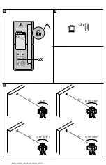
7.6.2 Setting the slope manually
4
Press the direction buttons (up/down) on the PRA 36
remote control to alter the angle of inclination quickly.
Pressing the arrow buttons for longer causes the values
to change more quickly.
NOTE
The angle of inclination cannot be read digitally.
7.6.3 Setting the slope automatically
15
NOTE
The slope can be set automatically only when slope mode
is active and when a PRA 36 laser receiver is used.
Nevertheless, bring the laser to the required angle of
inclination (as described in section 7.5.2).
NOTE
The angle of inclination cannot be read digitally.
7.6.4 Setting the slope with the aid of the
PRA 76/79 slope adapter
1. With the aid of the target notch on the head of the
PRI 36, bring the tool into alignment until parallel
with the inclined plane.
2. Press and hold the on / off button for at least 8
seconds until the “inclined plane mode” indicator
lights at top right of the control panel.
3. Set the desired angle of inclination on the slope
adapter.
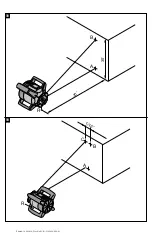
7.7 Surveillance
16
The surveillance function checks at regular intervals
whether an aligned plane (vertical or horizontal (hori-
zontal only in conjunction with the PRA 90 tripod)) has
shifted (e.g. due to vibration or temperature fluctuation).
If this is the case, the projected plane will be realigned to
the zero point (i.e. the marking notch on the PRA 36) (so
long as it is still within the receiving window). A PRA 36 is
required for use of the surveillance function. An additional
laser receiver can be used to detect the laser beam while
the laser beam is being monitored.
1. Preparation for activation of the surveillance function
is basically the same as the procedure for activation
of automatic alignment mode (see 7.5.2).
2. Position the tool at the desired starting point 1 and
switch it on.
3. Position the PRA 36 laser receiver at the reference
point (point 2) on the axis and secure it there. The
tool (point 1) and the PRA 36 (point 2) then form
anchor points on the plane. Take care to ensure that
the marking notch on the PRA 36 is at exactly the
height at which the rotating laser is later to project
the laser line or point. The green laser receiving
surface on the PRA 36 must face the rotating laser.
4. Take care to ensure there are no obstructions be-
tween the rotating laser and the PRA 36 laser re-
ceiver which could interfere with communication
between the devices. Glass and other translucent
materials may also interfere with communication be-
tween the devices. Reflections from windows may
also cause interference.
5. Switch the PRI 36 and the PRA 36 on. Surveil-
lance mode can be activated by double clicking the
“Surveillance mode” button on the PRA 36.
A further click is used to change the search direction
and a double click ends surveillance mode.
After the position has been reached (the marking
notch has been found) no further signal tone is
emitted.
6. The system is then in surveillance mode. The mode
is indicated in display of the PRA 36.
7. The surveillance system checks at regular intervals
whether the laser plane has shifted. If it is found to
have shifted, the laser plane will be readjusted to the
original marking plane as far as possible. If the laser
plane shifts to a position outside the laser receiving
window or direct line of sight between the rotating
laser and the laser receiver is obstructed for a long
period (>2 min), the laser stops rotating, a warning
triangle appears in the laser receiver display and
short signal tones are emitted.
NOTE
In order to ensure that the regular surveillance
process can be repeated automatically and of its
own accord, the PRA 36 should not be removed
from its position.
7.8 Returning to standard mode
In order to return to standard mode, horizontal alignment,
300 /min, the tool must be switched off and restarted.
7.9 Sleep mode
The PRI 36 can save power when in sleep mode. The
laser is switched off, thereby extending battery life.
Activate sleep mode by pressing the “Sleep mode” button
on the PRA 36.
Deactivate sleep mode by pressing the “Sleep mode”
button on the PRA 36 again.
After reactivating the PRI 36, check the laser settings in
order to ensure accuracy.
en
12
Printed: 14.04.2014 | Doc-Nr: PUB / 5162040 / 000 / 01
Summary of Contents for PRI 36
Page 2: ...1 Printed 14 04 2014 Doc Nr PUB 5162040 000 01...
Page 3: ...2 3 4 5 Printed 14 04 2014 Doc Nr PUB 5162040 000 01...
Page 4: ...6 7 8 9 10 11 Printed 14 04 2014 Doc Nr PUB 5162040 000 01...
Page 5: ...12 14 13 Printed 14 04 2014 Doc Nr PUB 5162040 000 01...
Page 6: ...35 15 D F E G 17 16 Printed 14 04 2014 Doc Nr PUB 5162040 000 01...
Page 7: ...18 5 19 5 Printed 14 04 2014 Doc Nr PUB 5162040 000 01...


