


Hardware Installation and Uninstalling
59/154
PC Cards cifX PC/104 | Installation, Operation and Hardware Description
DOC120206UM42EN | Revision 42 | English | 2014-12 | Released | Public
© Hilscher, 2008-2014
6.4 Installing PC Cards cifX PC/104 (PC/104 Modules)
Note:
For PC cards cifX PC/104 with AIFX assembly interface first install the basic card.
Then connect the AIFX assembly interface to the basic card.
1. Adhere to the necessary safety precautions for components that are
vulnerable with electrostatic discharge.
Electrostatically sensitive Devices
To prevent damage to the PC and the PC card cifX, make sure, that the
PC card cifX is grounded via the endplate and the PC and make sure,
that you are discharged when you install/uninstall the PC card cifX.
2. Configure starting address, interrupt and data bus width of the PC card
cifX PC/104
Configure the start address of the PC card cifX PC/104.
If you are using the interrupt mode, set up a free interrupt on the PC
card cifX PC/104.
For polling operation mode interrupt jumpers are not required.
Note:
Several PC/104 modules can be plugged one upon the other. For each PC card
CIFX 104-RE\F you must define a free memory area of 16 KByte.
For further information on the starting address and or an interrupt (or polling) refer to
section
cifX PC/104: Set Starting Address and Interrupt
on page 57.
Depending by the target system (motherboard) if so, set at the PC card
cifX PC/104 a
Data Bus Width
of 8 bit or 16 bit.
By default the jumper is set for a data bus width of 16 Bit (refer to chapter
Device Drawings
on page 38.
3. Take safety precautions.
Lethal Electrical Shock caused by parts with more than 50V!
Disconnect the power plug of the PC or of the connecting device.
Make sure, that the power supply is off at the PC or at the connecting
device.
4. Open cabinet.
Open the cabinet of the PC or of the connecting device.
Note:
If several PC/104 modules shall be put together in a stack:
(a) Install the first PC/104 module on the mainboard.
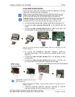
(b) Only for the basic cards CIFX 104-RE\F and CIFX 104-RE-R\F or the basic cards CIFX
104-FB\F and CIFX 104-FB-R\F: Connect the AIFX-RE, AIFX-DP, AIFX-CO, AIFX-DN, AIFX-
CC assembly interface or AIFX-DIAG to the basic card for the first PC/104 module.
(c) Connect any other PC/104 module on the respective underlying PC/104 module.
5. Install PC card cifX
PC/104
.
Plug the PC card cifX into a free PC/104 slot (or if so, to the underlying
PC/104 module).
Fix the PC card cifX using 4 spacing bolts and screws intended to the
mainboard (or if so, to the underlying PC/104 module). The scope of
delivery does not include spacing bolts and screws.


