4.1
Electrical Installation
4.1.1
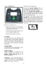
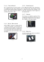
Handlebar
and
Compo-
nents
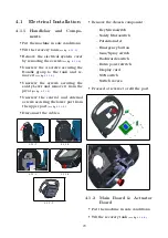
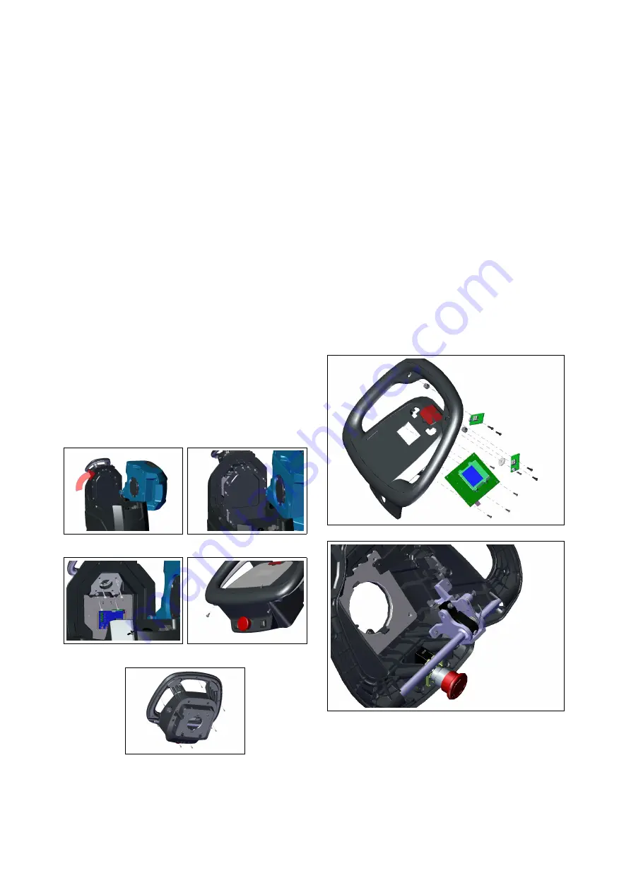
• Put the machine in safe conditions.
• Tilt the recovery tank
(see fig.
.
• Remove the electrical system cover
by removing the screws
(see fig.
.
• Unscrew the 4 screws securing the
Handle group to the tank and re-
move it
(see fig.
.
• Unscrew the screws securing the
safety Lever and remove it from the
pivot
(see fig.
.
• Unscrew the central and external
screws securing the lower part from
the upper part
(see fig.
.
• Disconnect the cables.
4.1.1-1
4.1.1-2
4.1.1-3
4.1.1-4
4.1.1-5
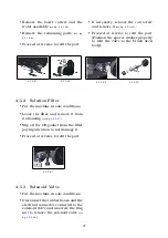
• Remove the chosen component:
–
Key Microswitch
–
Safety Microswitch
–
Potentiometer
–
Emergency button
–
Gun/Spray switch
–
Backwards switch
–
Extra power switch
–
Display card
–
SOS switch
–
Switch covers
• Proceed at reverse to refit the part.
4.1.2
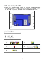
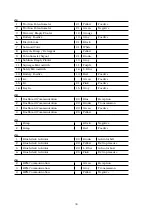
Main Board & Actuator
Board
• Put the machine in safe conditions.
• Tilt the recovery tank
(see fig.
.
20
Summary of Contents for TRIDENT T20SC PRO
Page 1: ...SERVICE MANUAL TRIDENT T20SC PRO Version AB Date November 7 2018 Document Number 10077483...
Page 4: ...Part I Product Introduction 4...
Page 8: ...Part II Anomalies Resolution Guide 8...
Page 28: ...Part III Machine Description 28...

