background image

4

Installation

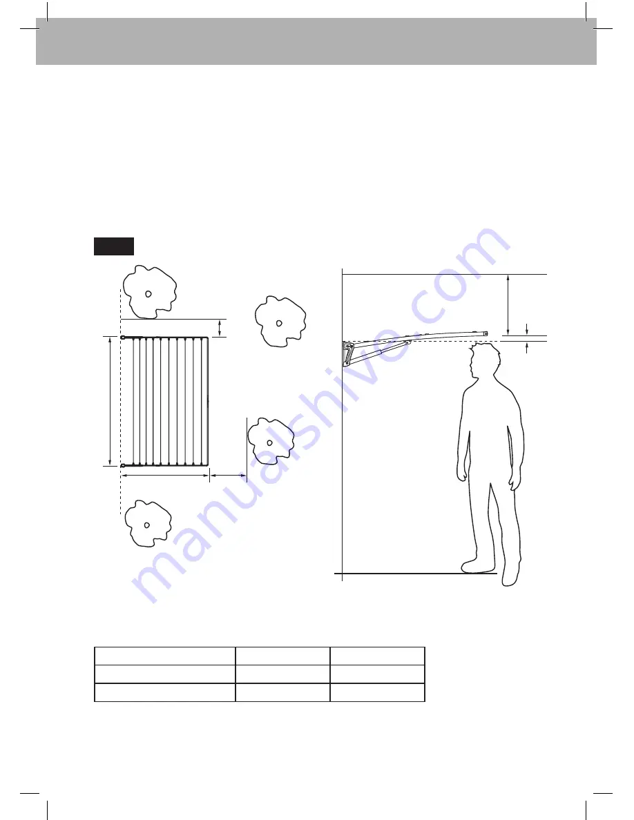
Step 1 – Select a suitable location 

Your Supa


Fold can be mounted to either a wall or post kit (sold separately).

You must check to ensure you have sufficient space in your garden / yard to install your 
clothesline (

Fig. 1

).

Your product can be reduced in width (if needed) refer to step 8 on page 12 for details.

We recommend mounting your Supa


Fold at a height approximately 50mm (2") above the 

head height of the intended user (

Fig. 1

).

Product

Width 

Depth 

Supa


Fold Duo

2250mm (88.5")

1200mm (47.2")

Supa


Fold Mono

2250mm (88.5")

1200mm (47.2")

Fig. 1

Depth

W

idth

Ensure area is free from  

pipes and obstructions

750mm  

(30") minimum

100mm 


(4") minimum

Product dimensions:

400mm (16")


minimum

50mm (2")

W

all or Post

Eaves or other overhang

•  User’s head height  

  = top of bracket

Ground

Summary of Contents for Supa Fold Duo

Page 1: ...3 417 Home Hardware Products Unit H 5 Butler Boulevard Burbridge Business Park Adelaide Airport South Australia 5950 Copyright ISSUE REF REVISION DATE RFC DWN CHK B A 1 Owner s Manual TO SUIT MODELS Supa Fold Duo Supa Fold Mono DETAIL B SCALE 2 5 6 D C B A 1 9 8 7 ISSUE REF REVI Premium Range Supa Fold Clotheslines ...

Page 2: ...llation to benefit from the design features and enjoy safe use of this product Thank you for choosing Hills Warning Do not allow children or pets to swing on the clothesline or items of laundry Ensure when raising and lowering your clothesline that bystanders in particular children are standing well clear Do not use for any purpose other than to hang and dry washing Do not use your clothesline if ...

Page 3: ...uter Spreader Bar 2 2 9 Spreader Joiner 2 1 10 Corner 4 2 11 Line 2 1 Hex Key 5mm 2 2 Hex Key 4mm 1 1 Line Tie Off Cap 4 2 Fasteners 4 4 Carton Contents Check all components are supplied in your carton Refer to the chart below for quantities 1 3 2 4 5 9 9 11 10 6 7 8 In the Supa Fold Duo model the fasteners are located in the wall bracket assembly Supa Fold Duo model shown for reference ...

Page 4: ...d refer to step 8 on page 12 for details We recommend mounting your Supa Fold at a height approximately 50mm 2 above the head height of the intended user Fig 1 Product Width Depth Supa Fold Duo 2250mm 88 5 1200mm 47 2 Supa Fold Mono 2250mm 88 5 1200mm 47 2 Fig 1 Depth Width Ensure area is free from pipes and obstructions 750mm 30 minimum 100mm 4 minimum Product dimensions 400mm 16 minimum 50mm 2 W...

Page 5: ...lation Fig 2 2 1 To remove the inserts simply hold the moulding and pull out 2 2 To re attach push the insert back into the bracket Warning When installing the brackets ensure the left and right labels are positioned correctly as shown Fig 2 Supa Fold Mono Supa Fold Duo Assembled Assembled Dis assembled Dis assembled Bracket Insert Bracket Insert ...

Page 6: ...ligned vertically and horizontally and use them as templates to mark where to drill holes a spirit level and straight edge will help User s head height to equal top of bracket Fig 3 Product Mount Hole Centres Supa Fold Duo 2200mm 86 5 Supa Fold Mono 2200mm 86 5 Refer to Fig 1 Important When installing a Supa Fold Duo take note of which holes are to be used for mounting of the mount brackets On the...

Page 7: ...ou are replacing an existing Hills Folding Frame product using the original fasteners ensure they are suitable and still in good condition For sound brick masonry walls we recommend using appropriate flush head 10mm diameter fasteners Fig 4 Fig 5 4 3 Drill appropriately sized holes in your wall to suit the fasteners being used Fig 4 4 4 Clear holes of dust and debris before inserting fastener Fig ...

Page 8: ...ur wall to suit the fasteners being used For timber stud walls we recommend using four 8mm 5 16 x 75mm 3 long wood screws For other stud and wall construction materials we recommend you consult your local hardware store for the appropriate fasteners When drilling into timber studs always drill a pilot hole to reduce the chance of the studs splitting It is critical that your Supa Fold mount bracket...

Page 9: ...ble the post kit as per the separate instructions provided with the kit 6 2 Install the mount brackets as shown Fig 7 Fig 7 Mount bracket M8 washer M8 x 75 socket head bolt M8 washer M8 nyloc Cross brace Hex key 6mm Single shown here for mono and duo fig7 for long compact and mini fig6 M8 x 55 socket head bolt Fasteners and Hex key supplied in Post Kit ...

Page 10: ... in further during the assembly of the second Spreader You must ensure the correct orientation of the spreader bars spreader joiner and mount holes The spreader joiner is designed to be a tight fit within the spreader bar so you may need to gently tap it in with a hammer Ensure you protect the other end of the spreader bar with a cloth soft surface or the cardboard packaging to avoid damage Ensure...

Page 11: ...end gently with a hammer as it s designed to be a tight fit Fig 11 Fig 11 Fig 12 Supa Fold Duo The Supa Fold Duo has an outer longer and inner shorter spreader bar Fig 12 You must ensure the lengths of spreader bars match Inner shorter Outer longer Outer longer Ensure fastener hole is in correct orientation Inner shorter ...

Page 12: ...he assembled spreader with a hacksaw Fig 14 For the Supa Fold Duo model you will need to cut both the inner and outer assembled spreader bars Cutting equal amounts from each end of the spreader will maintain the spreader handle in the centre of the product Be careful when cutting with a hacksaw ensure you do not slip damage the powdercoat and keep the cut edge square You may need to clean up the e...

Page 13: ...ex key provided Refer to Fig 15 and Fig 16 Do not over tighten the fasteners as the arms and struts must be free to pivot In this manual left and right side is referenced as if you are looking at your clothesline ie at the wall post kit you are assembling to Repeat for other arm Fig 15 Fig 16 Supa Fold Duo Supa Fold Mono Strut Arm Mount bracket Small fastener Large fastener 5mm hex key Mount brack...

Page 14: ...ly levering with a screwdriver Fig 18 10 2 Insert and secure the corners into both ends of the spreader bar using hex key 5mm ensure bolts are firmly tightened Fig 19 Fig 18 Fig 19 Corner cap Hex key 5mm Spreader bar M6 socket head bolt Insert screwdriver into slot and gently lever open ...

Page 15: ... strut clicks once to indicate it has engaged then lower gently to the horizontal position Fig 20 11 2 Insert the spreader bar and corners into the arm ends and secure using hex key 5mm Fig 21 Please note the correct handle orientation 11 3 Snap on all corner caps with Hills logo up Fig 22 Fig 20 Fig 21 Fig 22 Corner cap Corner Spreader bar Arm click ...

Page 16: ...ading patterns as shown Fig 23 Each line is fastened to a line tie off then threaded through the line sleeves and tensioned fastened to the other line tie off Fig 23 Supa Fold Duo Supa Fold Mono Line tie off Line tie off Line tie off Line tie off Line tie off Line tie off Line sleeves Line sleeves Line sleeves ...

Page 17: ...e line into the slot of the line tie off saddle and through the side Pull through 15cm of excess line for tensioning 12 3 Loop the line around the groove in the line tie off saddle Pull tight to prevent the line from slipping 12 5 Continue feeding the line through the line sleeves ensuring all lines are parallel refer to Fig 23 for the threading pattern for your product Note It is useful to kink o...

Page 18: ...into the line tie off saddle 12 10 Push PVC line end securely into saddle 12 11 Fit line tie off caps over the line tie off saddles Step 12 Continued 12 8 Check that all the lines are tight and adjust and retension if necessary 12 7 Insert the line into the slot of the last line tie off saddle repeat the tie off ...

Page 19: ...ition To raise the clothesline Fig 24 A Loosely grip the spreader bar handle B Pull the frame away from the wall slowly and raise it above your head until you hear both struts click once to indicate they have engaged C Now lower the frame slightly if both struts have fully engaged the frame will be supported squarely If the struts did not engage on both sides repeat the process Fig 24 Raising your...

Page 20: ...n metal components we recommend a twice yearly application of a reputable brand of car polish or wax Line Tensioning To remove any excess slack from the lines feed the line through the Line Sleeves until desired tension is achieved Undo and re tie line as shown in step 12 on pages 17 and 18 Do not over tension the line as you may distort the frame Hills Handy Hints Place smaller items of clothing ...

Page 21: ... attachment to this product has Hills specific approval or is sold as a Hills product the warranty on this product is waived The product is designed to perform a specific task under established test loads and unauthorised attachments may produce stresses for which the design is not appropriate Designs specifications and colours are subject to change without notice Please retain this Owner s Manual...

Page 22: ...22 Notes ...

Page 23: ...23 Notes ...

Page 24: ...Hills Holdings Limited A B N 35 007 573 417 Issue March 2011 PD2991c ...

Reviews: