Hill Phoenix 05DMA Installation & Operating Handbook Download Page 18

14

Alarm Operation

Indications on the Display

If the defrost, or compressor key blinks, it means that the
corresponding function is delayed by a timing routine or
inhibited.  Other two-character messages may appear on
the screen to indicate changes of state or alarm condi-
tions.  Values shown in Table 1.

Viewing and Changing the Temperature Setpoint

The temperature setpoint is the comparison point for the
control temperature input. To change the set point value:

1. Press the 

Alarm

key for more than 5 seconds until the

setpoint is displayed and blinking.

2. Press the 

Compressor

key and Defrost keys to 

raise/lower the value.

3. Press the 

Alarm

key again to accept the new value.

Changing Other Setpoints

There are two levels of setpoints in the ESC3. The first
level does not require a password to change (unless the
buttons are locked out). The setpoints that can be
changed in this manner are identified in Table 1 (back
side) as a USER setpoint. All other setpoint do require a
password to change and are identified in Table 2 (back
side) as an OEM setpoint.  To change USER-level set-
points:

1. Press the 

Alarm

key and hold it until the letters PS are

displayed.

2. Use the 

Compressor

and 

Defrost

key to scroll through

the codes for the different set points (see Table 1 and
Table 2).

3. When the code is displayed for the setpoint you wish to

change, press the 

Alarm

key. The value for that

setpoint will be displayed.

4. Press the 

Compressor

or 

Defrost

key to change the 

value

5. Press the 

Alarm

key to go back to the code.

At this point you must press the 

Alarm

key to accept the

change or press the 

Compressor

or 

Defrost

key to scroll

to the next USER setpoint. To accept the changes, press
and hold the 

Alarm

key until the display stops flashing.  To

change OEM-level setpoints, the password must be
entered. To do this press and hold the 

Alarm

key until the

letters PS are displayed. When PS is displayed release
the alarm key and 0 will be displayed. Press the

Compressor

or 

Defrost

keys to enter the password (22 is

the default) then press the 

Alarm

key. PS will be dis-

played again. At this point, pressing the 

Compressor

or

Defrost

key will scroll through the legend for all setpoints.

To change the setpoints, use the identical procedure that
is used to change a USER setpoint.
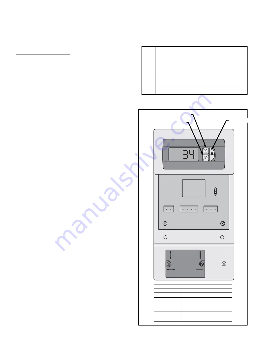
Code

Meaning

E0

Air probe has failed

E1

Defrost termination or product probe has failed

LO

Low temperature alarm

HI

High temperature alarm

Ed

Defrost timeout has occurred
(did not terminate correctly)

dF

Case is in defrost (not an alarm)

Table 1

K1

J4

J6

J5

R1

K2

1

5

4

6

120V

ac

Neutral

Fan

Compressor

120V Hot

Defrost

Amb temp

Common

Def temp

ESC3 Case Controller

Alarm Key

Defrost Key

Compressor Key

Control Input

0.39 A, 120 Vac, 60 Hz

Common Input

11.2 A, 120 Vac, 60 Hz

Fan Output

1 FLA, 6 LRA, 120 Vac, 60 Hz

Compressor Output

1.5 HP @ 120 Vac

(K2)

(external relay #841-S-1A-D
by Song Chuan)

Defrost Output

10.0 A, 120 Vac, Resistive, 60 Hz
(P/N 850-3500 only)

CONTROL SETTINGS

ESC3 Controls

Summary of Contents for 05DMA

Page 1: ...DAIRY DELI PRODUCE C A S E S MODEL O5DMA HANDBOOK INSTALLATION OPERATION P056442G Rev 10 12 04...

Page 2: ...fore cleaning case HIGH PRESSURE HIGH PRESSURE WARNING Some surfaces may be hot when case is in operation HIGH PRESSURE WARNING Always turn off power to lights before servicing HIGH PRESSURE DANGER El...

Page 3: ...o make it easier to read and to help you get the most from this innovative new design When you follow the instructions you should expect remarkable performance attractive fits and finish and long case...

Page 4: ......

Page 5: ...S PAGE 7 Operational descriptions of the refrigeration components PLUMBING PAGE 8 Information on drain connections ELECTRICAL HOOKUP CONTROL SETTINGS AND WIRING DIAGRAMS PAGES 9 16 Complete informatio...

Page 6: ...1109 APPARENT DAMAGE A claim for obvious damage must be noted on the freight bill or express receipt and signed by the carriers agent otherwise the carrier may refuse the claim CONCEALED DAMAGE If dam...

Page 7: ...13 1 cm COIL PLENUM 6 13 16 in 17 2 cm 43 1 4 in 109 9 cm 32 in 81 3 cm 59 in 149 9 cm 3rd ROW LIGHT OPTIONAL 9 75 MIRROR OPTIONAL 13 MIRROR OPTIONAL 14 1 2 in 36 9 cm 18 11 16 in 47 5 cm 55 13 16 in...

Page 8: ...ERS MAY BE DISCARDED ROLL OUT OF TRUCK When there is a truck level delivery dock cases may be rolled directly from the truck to the store floor CAUTION If skid boards are required to unload cases cast...

Page 9: ...rail See illustration 1 below for details When installing the upper kickplate retainer make sure it is placed behind the front panel lip as shown in illustration 1 below The end kickplates which are...

Page 10: ...e expansion valve and other controls are located on the left hand side of the case and are accessible without lifting the fan plenum The controls cluster may be reached by lifting only the left hand d...

Page 11: ...at transfer Filter Drier A device installed on the liquid line of a refrigeration system that removes water and other impurities from the refrigerant in the lines during initial start up Receiver The...

Page 12: ...e issues arise care should be given to assure that all connections are water tight and sealed with the appropriate PVC or ABS cement The case run off is channeled to a drain pan located underneath the...

Page 13: ...nd not as a power supply for peripheral equipment FIELD CONNECTION JUNCTION BOX DRAIN PUMP RECEPTACLE DANGER Electrical Shock Hazard Always disconnect power to case when servicing or cleaning HIGH PRE...

Page 14: ...reflectors may be easily removed be removing a several screws along the length of the reflector See below 1 Remove lamps by pulling down at both ends 2 Remove screws along length of the reflector 3 R...

Page 15: ...s dd Maximum Defrost Duration 1 to 99 min dC Dripping Time After Defrost 0 to 99 min dU Initial Defrost Interval time before first defrost after startup 0 to 99 min dP Defrost Display 0 displays last...

Page 16: ...test Cycle power to resume operation Press the Up and the Down buttons in sequence and hold for 5 seconds To Initiate Self Test Press and the Enter and Up buttons in sequence and hold for five seconds...

Page 17: ...lished by com paring the temperature reading of the case temperature probe against the temperature setpoint The compressor out put is used to control the temperature If the temperature is above the te...

Page 18: ...r that setpoint will be displayed 4 Press the Compressor or Defrost key to change the value 5 Press the Alarm key to go back to the code At this point you must press the Alarm key to accept the change...

Page 19: ...d defrost dd Drip time 0 15 min d8 Alarm delay after defrost 0 15 hours d Defrost probe reading read only C F AL Low temperature alarm differential subtract this value from the temperature 0 127 C F s...

Page 20: ...16 WIRING DIAGRAMS MODEL O5DMA...

Page 21: ...Fail safe min 4 Termination Temp F Defrost Controls All measurements are taken per CRMA specifications Medium Temperature Defrost Schedule No Per Day Hours 1 12 midnight 2 12 am 12 pm 3 6 am 2 pm 10 p...

Page 22: ...ess to the probe can be gained by removing the lower rear baffle The temperature control probe is located behind the 3 1 2 plug button in the top flue panel also shown in the diagram below Both of the...

Page 23: ...not overload the food product display so that it impinges on the air flow pattern DISCHARGE 1 LOAD LIMIT 2 AIR FLOW 3 RETURN AIR GRILL 4 MODEL O5DMA Overloading will cause malfunction and the loss of...

Page 24: ...RE CLEANING PROCEDURES A periodic cleaning schedule should be established to maintain proper sanitation insure maximum operating efficiency and avoid the corrosive action of food fluids on metal parts...

Page 25: ...ch be maintained as specified Do not attempt a field modification by altering the blades Fan motors may be changed with an easy two step process without lifting up the plenum thereby avoiding the nece...

Page 26: ...E09 E11 E10 E20 50 E06 E07 22 PARTS ORDERING 11 24 9 1 26 2 17 19 22 15 12 13 20 25 51 3 88 87 38 82 E19 81 36 86...

Page 27: ...or Unlighted Painted White Custom Color or Stainless 24 J Rail for Kickplate 25 Top Flue Panel Painted White Custom Color or Stainless 26 Front Panel Curved Shown or Flat Painted Custom Color 36 Plug...

Page 28: ...of the case on which the part is used Length of part if applicable I E 4 6 8 Color of part if painted or color of polymer part Whether part is for left hand or right hand application Whether shelves...

Page 29: ...25 NOTES...

Page 30: ...26 NOTES...

Page 31: ...sales tax or upgrading 5 When the operation is impaired due to improper installation 6 When installation and startup forms are not properly complete or returned within two weeks after startup THIS PLA...

Page 32: ...cleaning cases the following must be performed PRIOR to cleaning To avoid electrical shock be sure all electric power is turned off before cleaning In some installations more than one switch may have...

Reviews: