Control Terminal’s User Manual
13
3.3
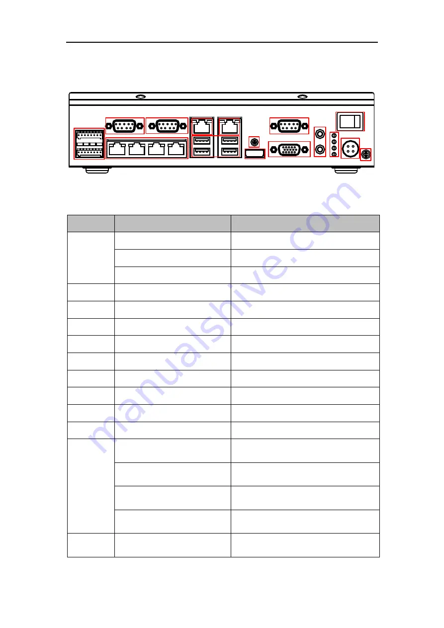
Interface Description
1
2
3
5
6
4
7
8
9
10
11
12
13
15
16
14
Figure 3-3
Interface Introduction
Figure 3-4
Interface Description
No.
Name
Description
1
ALARM OUT
4-ch alarm outputs
ALARM IN
2-ch alarm inputs
RS-485
2 RS-485 interfaces
2/3/10
RS-232
3 RS-232 interfaces
4
LAN1
4 10/100M Ethernet Interfaces
5
G1
10/100/1000M Ethernet Interface
6
G2
100/1000M Ethernet Interface
7
USB
USB Interface
8
Screw
Lock Screw
9
HDMI
HDMI
11
VGA
VGA Interface
12
AUDIO IN/OUT
1-ch audio input/output
13
Power Indicator
Indicator goes to green if power is
connected.
Alarm Indicator
Indicator goes to red if the alarm is
triggered.
HDD Indicator
The green indicator flashes when
HDD is working.
Working Status Indicator
The indicator stays in green when the
device is working normally.
14
POWER
Power switch, press 5 seconds to turn
on/off the device.


