background image


Video Intercom Door Station

·

User Manual


38 


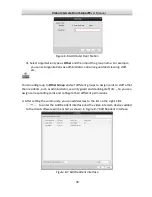
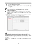
Figure 8-4


Group of Community 

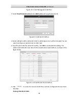
3.


Select the group type and click 

  to add group, input the corresponding information 

accordingly. 
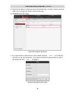
1).


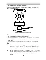
Select group type as Community and then Input the Project No., Community No., 

and Building No. to set the community structure, as shown in Figure 8-5 Add 
Building. 


Figure 8-5


Add Building 

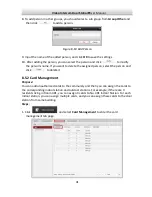
2).


Select group type as Outer Door Station and then input the outer door station 

name (Range: 1-9) to set the outer door station, as shown in Figure 8-6 Add 
Outer Door Station. 

Summary of Contents for DS-KV8102-1A

Page 1: ...UD 6L0206D1033A01 Video Intercom Door Station V Series User Manual ...

Page 2: ...are registered trademarks or the subject of applications for the same by Hikvision and or its affiliates Other trademarks mentioned in this manual are the properties of their respective owners No right of license is given to use such trademarks without express permission Disclaimer TO THE MAXIMUM EXTENT PERMITTED BY APPLICABLE LAW HIKVISION MAKES NO WARRANTIES EXPRESS OR IMPLIED INCLUDING WITHOUT ...

Page 3: ...E OF OR RELIANCE ON THIS MANUAL EVEN IF HIKVISION HAS BEEN ADVISED OF THE POSSIBILITY OF SUCH DAMAGES SOME JURISDICTIONS DO NOT ALLOW THE EXCLUSION OR LIMITATION OF LIABILITY OR CERTAIN DAMAGES SO SOME OR ALL OF THE ABOVE EXCLUSIONS OR LIMITATIONS MAY NOT APPLY TO YOU Support Should you have any questions please do not hesitate to contact your local dealer 0100001050608 ...

Page 4: ...ause undesired operation EU Conformity Statement This product and if applicable the supplied accessories too are marked with CE and comply therefore with the applicable harmonized European standards listed under the Low Voltage Directive 2006 95 EC the EMC Directive 2004 108 EC the RoHS Directive 2011 65 EU 2012 19 EU WEEE directive Products marked with this symbol cannot be disposed of as unsorte...

Page 5: ...e product is installed on wall or ceiling the device shall be firmly fixed If smoke odors or noise rise from the device turn off the power at once and unplug the power cable and then please contact the service center If the product does not work properly please contact your dealer or the nearest service center Never attempt to disassemble the device yourself We shall not assume any responsibility ...

Page 6: ...he acidic sweat of the fingers may erode the surface coating of the device cover Please use a soft and dry cloth when clean inside and outside surfaces of the device cover do not use alkaline detergents Please keep all wrappers after unpack them for future use In case of any failure occurred you need to return the device to the factory with the original wrapper Transportation without the original ...

Page 7: ...ith Gang Box of DS KV8X02 1A Model 8 5 2 Installation of DS KV8102 XC Model 9 5 2 1 Installation Plate for DS KV8102 XC Model 9 5 2 2 Wall Mounting with Gang Box of DS KV8102 XC Model 10 5 3 Wiring 12 5 3 1 Door Lock Wiring 12 5 3 2 Door Magnetic Wiring 13 5 3 3 Door Switch Wiring 13 5 3 4 Wiring of Alarm Device Input 14 6 Before You Start 15 7 Batch Configuration Tool 15 7 1 Activate the Device 1...

Page 8: ... 41 8 6 Notice Management 48 8 6 1 Query Unlocking Log 48 8 7 Device Arming Control 48 9 Basic Operation 51 9 1 Calling Resident 51 9 1 1 Calling Resident Device DS KV8X02 1A 51 9 1 2 Calling Resident Device DS KV8102 XC 52 9 2 Issuing Card 53 9 3 Door Unlocking by Swiping Card 53 Appendix 54 Installation Notice 54 Wiring Cables 54 Specification 54 ...

Page 9: ...tation is mainly applied in situations such as community villa and official buildings 1 2 Main Features Support video intercom function HD video surveillance Max resolution 1280 720 25fps WDR 120 wide angle Auto self adaptive light supplement White Light IR Supplement Support access control function Supports issuing card function via local station Auto upload captured picture while unlocking the d...

Page 10: ... 3 4 5 6 7 8 Figure 2 1 Appearance of Door Station Description of Door Station Models No Description DS KV8102 1A DS KV8202 1A DS KV8402 1A 1 Low Illumination Supplement Light 2 Built in Camera 3 Swiping card Area 4 Calling Button 5 Loudspeaker 6 Room Number Customized 7 Microphone 8 Tamper proof Button ...

Page 11: ... Station DS KV8102 XC 1 2 3 4 5 6 Figure 2 2 Appearance of Door Station Description of Door Station Models No Description DS KV8102 1C DS KV8102 2C 1 Microphone 2 Low Illumination Supplement Light 3 Built in Camera 4 Swiping card Area 5 Calling Button 6 Loudspeaker ...

Page 12: ...dent 2 Resident 1 Indoor Stations Network Cable Door Station Connect to the LAN of Community via Optical Fiber Optical Fiber Main Door Station Figure 3 1 Typical Application 3 2 Typical Application of Door Station DS KV8102 XC Please refer to the following figures for typical applications of DS KV8102 1C DS KV8102 2C door station DS KV8102 1C DS KV8102 2C door station can also work as doorphone Pl...

Page 13: ...Fiber Optical Fiber Figure 3 2 Typical Application 1 Resident 2 Resident 2 Resident 2 Resident 2 Indoor Stations Network Cable Doorphones Connect to the LAN of Community via Optical Fiber Optical Fiber 4F 3F 2F 1F 1F G Resident 1 Resident 1 Resident 1 Resident 1 Connect to Door Station Outer Door Station Figure 3 3 Typical Application 2 ...

Page 14: ...LUE ALARM_1 2 YELLOW ORANGE ALARM_2 3 YELLOW GREEN ALARM_3 4 YELLOW BROWN ALARM_4 5 YELLOW BLACK ALARM_GND Power Supply 6 RED 12V DC Power Supply Input GND 7 BLACK Grounding RS485 8 ORANGE RS485 9 YELLOW RS485 ALARM OUT 10 PINK DR_NC 11 BLUE DR_NO 12 BROWN DR_COM LAN 13 LAN Network Interface 4 IO Input terminals ALARM_1 ALARM_4 can be set as door magnetic input or door switch key input and termina...

Page 15: ...lize a matched gang box 5 1 1 Gang Box for DS KV8X02 1A Model Please refer to the following figures for the dimensions of gang box for DS KV8102 1A DS KV8202 1A DS KV8402 1A door station 89 168 49 54 97 50 45 100 73 92 Figure 5 1 Front View Rear View The dimension of gang box for model DS KV8102 1A DS KV8202 1A DS KV8402 1A door station is 89 width 168 length 38 depth mm ...

Page 16: ...rom the packing box 2 Chisel a hole in the wall for inserting the gang box The size of the hole should be 90 width 170 length 38 depth mm 3 Insert the gang box into the hole and fix it with 4 PA4 screws as shown in the figure below PA4 Screws Figure 5 2 Insert the Gang Box 4 After fixing the gang box install the door station into the gang box according to the direction of the arrow as shown in the...

Page 17: ...xing screw according to the direction of the arrow of the figure below M4 Screw Figure 5 4 Secure the Door Station 5 2 Installation of DS KV8102 XC Model 5 2 1 Installation Plate for DS KV8102 XC Model To install the DS KV8102 XC model onto the wall an installation plate and a gang box are required Please refer to the following figures for the dimensions of the installation plate of DS KV8102 XC d...

Page 18: ...nsions above are theoretical The actual size can be slightly different from the theoretical dimension 5 2 2 Wall Mounting with Gang Box of DS KV8102 XC Model Steps 1 Take the gang box installation plate and screws from the packing box 2 Chisel a hole in the wall for inserting the gang box The size of the hole should be 76 width 76 length 50 depth mm 3 Insert the gang box into the hole as shown in ...

Page 19: ... installation plate onto the gang box The KA4 screw is optional PA4 Screws KA4 Screw Figure 5 7 Attach the Installation Plate 6 After installing the installation plate install the door station by inserting the rear component into the hollow area of the installation plate While inserting the door station into the installation plate incline the device by 5 10 as shown in the figure below Hollow Area...

Page 20: ...he fixing screw according to the direction of the arrow of the figure below KM3 Screw Figure 5 9 Secure the Door Station 5 3 Wiring 5 3 1 Door Lock Wiring Please refer to the following figure for door lock wiring Electric Strike Magnetic Lock Electric Bolt Figure 5 10 Door Lock Wiring ...

Page 21: ...h video intercom configuring tool software or iVMS 4200 client software 5 3 2 Door Magnetic Wiring Please refer to the following figure for door magnetic wiring ALARM_GND ALARM_n Figure 5 11 Door Magnetic Wiring To connect door magnetic in terminal ALARM_n ALARM_1 ALARM_4 ALARM_GND it is required to set the input of terminal ALARM_n ALARM_1 ALARM_4 ALARM_GND to be magnetic door with video intercom...

Page 22: ...4 ALARM_GND it is required to set the input of terminal ALARM_n ALARM_1 ALARM_4 ALARM_GND to be door switch button with video intercom configuring tool software or iVMS 4200 client software 5 3 4 Wiring of Alarm Device Input Please refer to the following figure for NO detector wiring ALARM_n ALARM_GND Alarm Devices Figure 5 13 Wiring of Alarm Device Input ...

Page 23: ...s to the device via internet with Batch Configuration Tool iVMS 4200 or other client software you should firstly activate the device and set the device password Please refer to 7 1 for creating the password 7 Batch Configuration Tool 7 1 Activate the Device Purpose The operation of door station cannot be performed when the device is not activated Please activate the device and set the device passw...

Page 24: ... weekly can better protect your product 3 Confirm the password 4 Click OK to activate the device When the device is not activated the basic operation and remote operation of device cannot be performed 7 2 Adding Device The software provides 4 ways for adding the devices You can add the active online devices within your subnet add devices by IP address add devices by IP segment or add devices by de...

Page 25: ...on interface the active online devices within your subnet display in the Online Devices list in the lower part of the interface Figure 7 3 Online Devices Interface 3 You can click to select a device or hold the Ctrl or Shift key to select multiple devices and then click to pop up the Login dialog box Figure 7 4 Login Dialog Box ...

Page 26: ...P Address in the Adding Mode drop down list input the IP address in the IP Address field and set the port No user name and password of the device Figure 7 5 Adding by IP Address 2 Click OK to add the device to the device list Task 2 Add by IP Segment Purpose You can simultaneously add many the devices whose IP addresses are among the IP segment Steps 1 Select IP Segment in the Adding Mode drop dow...

Page 27: ... access to the network via port mapping you can simultaneously add them by this method In this way you can add many devices with the same IP address while with different port No Steps 1 Select Port No in the Adding Mode drop down list enter the IP address define the port No range in the Start Port No and End Port No field and set the user name and password You cannot add the device s to the device...

Page 28: ...search and add the devices of which port numbers are within the defined port No range to the device list The user name and password of the devices added by IP segment should be identical When you add devices by IP Address the devices should be online devices ...

Page 29: ...rs and click Edit NET Parameters Figure 7 8 Edit NET Parameters 2 Input new IP Address Subnet Mask Gateway Address Port No and the password Click OK to accomplish the editing Figure 7 9 Edit Network Parameters The default Port No is 8000 After editing the network parameters of device you should add the devices to the device list again 7 4 Remote Configuration In the device list area select a devic...

Page 30: ...nformation General Time System Maintenance User RS485 Device Information Click to enter device basic information interface You can view the device type serial No and version information Figure 7 11 Device Basic Information Interface General Click to enter device information interface You can view and edit the device name and device ID Figure 7 12 Device Information Interface ...

Page 31: ...erver address NTP Port and synchronization interval Click Apply to accomplish the time setting Figure 7 13 Time Setting Interface The default Port No is 123 The default synchronization interval is 60 min System Maintenance Purpose You can operate the system management and remote upgrading Steps 1 Click to enter the system maintenance interface ...

Page 32: ... to restore the default parameters 4 Click to restore all parameters of device and reset the device to inactive status 5 Click and the import file window pops up Select the path of remote configuration files 6 Click Open to import the remote configuration file The configuration file is imported and the device will auto reboot Figure 7 15 Import Configuration File Window ...

Page 33: ...ation File Window 8 Click to select upgrade file and click to remote upgrade the device The process of remote upgrade will be displayed in the process bar Figure 7 18 Remote Upgrade Click Restore Default Settings the device will be restore to default settings But the network parameters will not be restored Click Restore All the device will be restore to default settings and the network parameters ...

Page 34: ...20 User Parameter Interface 3 Input new password and confirm password in the textbox and click Apply to accomplish the editing of password The new password and confirm password should be identical After editing the password of device click button from the device list the added device will not be there You should add the device again with new password to operate the remote configuration RS485 Click...

Page 35: ... interface 2 Input the Room No of indoor station Figure 7 22 Configure Device Number Door Station V Series 3 Select Yes from the dropdown list of Auto Login and click Apply to enable the Number Configuration For main door station V Series the serial No is 0 For sub door station V Series the serial No is higher than 0 Serial No range from 1 to 99 For each villa at least one ...

Page 36: ... supported for using only as door station V Series Time Parameters Click to enter the time parameters interface You can configure the maximum ring duration and maximum live view time Figure 7 23 Time Parameters Maximum ring duration is the maximum duration of indoor station when it is called without being received The range of maximum ring duration varies from 15s 60s Maximum live view time is the...

Page 37: ...or Click to enter the interface of setting parameters of access control and elevator You can configure the parameters of access control and elevator Figure 7 25 Interface of Access Control and Elevator Configuration IO In and Out Click to enter the IO in and out interface Figure 7 26 IO In and Out Interface ...

Page 38: ..._NO interface of door station You can enable disable IO Out or set IO Out as electric lock by selecting from the dropdown list Volume In and Out Click to enter the volume in and out interface Slide the slider to adjust the volume input and volume output Figure 7 27 Volume In and Out Interface Calling Buttons Click Calling Buttons to enter the calling buttons settings interface Select the calling b...

Page 39: ...figuration Linked Devices Network Configuration Purpose In the linked devices network configuration interface you can configure the network parameters of master stations SIP servers and management centers of the same LAN The devices can be linked to the door station and realize the linkage between these devices Steps 1 Click to enter the devices network configuration interface the linked devices n...

Page 40: ... center and indoors After adding management center IP Address the events can be uploaded to the management center FTP Steps 3 Click to enter the FTP parameter interface the FTP parameter interface is shown in the Figure 7 31 4 Select IP Address from the dropdown list of Server mode and input the FTP server IP Address Port No 5 Check the checkbox to enable the anonymity optional Select the director...

Page 41: ...ps 1 Click of menu to enter the video parameters interface the video parameter interface is shown in the Figure 7 32 2 Select the Camera No and configure the format hue brightness contrastness saturation sharpness and denoising or click to restore default settings 3 Click Apply to accomplish the setting ...

Page 42: ...Video Intercom Door Station User Manual 34 Figure 7 32 Video Parameters Interface ...

Page 43: ...You can configure the ringtone Max ring duration Max speaking time with indoor station and Max speaking time with door station Figure 8 1 System Configuration Interface 8 2 Device Management Device management includes device activation adding device editing device deleting device and remote configuration Please refer to Chapter 7 Batch Configuration Tool for detailed information To add door statio...

Page 44: ...eps 1 Enter the main view interface of iVMS 4200 client software to display the live view of door station V Series Figure 8 2 Live View of Door Station V Series 2 Right click on the live view interface to display the menu and select Unlock Door to remote unlock the door ...

Page 45: ...ture will be uploaded to the storage server 8 5 Group Management Enter Control Pane l Operation and Control Video Intercom Group Management to add edit and delete groups 3 group types can be selected building outer door station and other Here we take the building as an example 8 5 1 Assigning Devices to Group 1 Click and select Group Management to enter the group management tab page 2 The group of...

Page 46: ...rdingly 1 Select group type as Community and then Input the Project No Community No and Building No to set the community structure as shown in Figure 8 5 Add Building Figure 8 5 Add Building 2 Select group type as Outer Door Station and then input the outer door station name Range 1 9 to set the outer door station as shown in Figure 8 6 Add Outer Door Station ...

Page 47: ...t different groups to assign cards to staff other than residents such as administrator security guard and cleaning staff etc So you can assign corresponding cards and configure their different permissions 4 After setting the community you can add devices to the list on the right Click to enter the Add Resident Interface and the video intercom devices added to the client software will be listed as ...

Page 48: ...tation No to assign the devices to the community 6 Click OK to save the setting Figure 8 8 Assigned Residents 7 You can select the indoor station or door station and click to modify the room No or the door station No If you want to delete the assigned device select the device and click to delete it Figure 8 9 Modify the Room No ...

Page 49: ...nt to delete the assigned person select the person and click to delete it 8 5 2 Card Management Purpose You can add unauthorized cards to the community and then you can assign the cards to the corresponding indoor station and outdoor stations For example if there are 3 residents living in Room 401 you can assign 3 cards to No 401 Indoor Station For each indoor station you can assign multiple cards...

Page 50: ...tch add single card or with card reader You can select card type as resident card or other card 4 Input the start card No and end card No click OK to accomplish the adding The added card information are listed in the unauthorized card interface as shown in the figure below Figure 8 13 Unauthorized Card Interface 5 Click to enter the issue card interface as shown in Figure 8 14 Issue Card Interface...

Page 51: ...d Interface 2 Click to assign cards to the indoor station You can assign multiple cards to one indoor station 3 Check the checkboxes of the cards you need to assign to the indoor station and check the checkbox of door stations doorphones and outer door stations only resident cards can be assigned to indoor stations 4 Click Issue Card to complete the card issuing operation ...

Page 52: ...ed in the resident list Figure 8 16 Issue Card Interface 2 Click to assign cards to the organization You can assign multiple cards to one person 3 Check the checkboxes of the cards you need to assign to the person and check the checkbox of door stations doorphones and outer door stations only other cards can be assigned to person 4 Click Issue Card to complete the card issuing operation ...

Page 53: ...e Cards 1 Click to enter the card issuing interface Figure 8 18 Issue Card Interface 2 Select the Community from groups to delete normal cards and select Other from groups to delete other cards 3 To cancel certain cards or single card click the button to enter the card selection interface ...

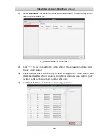
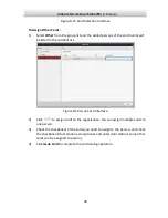
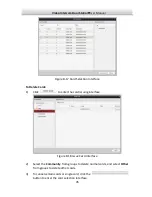
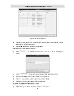
Page 54: ...peration To Batch Import Unauthorized Cards 1 Click to enter the batch import interface as shown in the figure below 1 Click to export the template of the batch import file 2 Fill in the template of the batch import file and save it 3 Click to select the batch import file and click Open 4 Click OK to start importing the batch import file To Batch Export Unauthorized Cards 1 After adding unauthoriz...

Page 55: ...l be reset to unauthorized card 6 Click Normal Card to display normal card list After issuing cards the issued cards will be listed in the normal card list as shown in the figure below Figure 8 20 Normal Card Interface To assign the cards with card issuer please connect the card reader DS K1F100 D8 purchased separately to PC via USB interface Open iVMS 4200 and enter the directory of Video Interco...

Page 56: ...uery unlocking logs interface 2 Select the unlocking type device type and set the start time and end time Figure 8 21 Query Unlocking Logs 3 Click Query to search the unlocking log 4 Click Export to export the unlocking logs 8 7 Device Arming Control Steps 1 Select Tool Device Arming Control to enter the device arming control interface ...

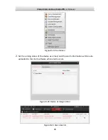
Page 57: ...ser Manual 49 Figure 8 22 Tool Menu 2 Set the arming status of the device as armed and the alarm information will be auto uploaded to the client software when alarm occurs Figure 8 23 Device Arming Control Figure 8 24 Alarm Events ...

Page 58: ...Video Intercom Door Station User Manual 50 After adding the device to the client software it will be armed automatically ...

Page 59: ...A there is only 1 calling button For device DS KV8202 1A there are 2 calling buttons For device DS KV8402 1A there are 4 calling buttons Calling Button Room Number Figure 9 1 Calling Button of DS KV8402 1A Steps 1 Press the corresponding calling button of the resident you need to call 2 The video intercom between you and the resident will be realized You can speak to the resident and the live view...

Page 60: ...w of door station will be displayed on the connected indoor station 3 The resident can receive decline the video call unlock the door call elevator etc When live view of door station is displayed on other devices or door station is calling resident the door station will detect the brightness of video When the brightness is lower than the expected threshold the supplement light will be enabled When...

Page 61: ...nd added to the device automatically After issuing each card successfully the device plays the voice prompt Issuing card finished 3 When the issued card amount exceeds the upper limit the device plays the voice prompt Card amount exceeds limit No more than 16 cards can be issued to the V series door station 4 Swipe the main card again or perform no operation for more than 10s the device will exit ...

Page 62: ...and master station Wiring Cables Cable Specification Power Cord of Door Station RVV 2 1 0 Network Cable of Door Station UTP five Categories Door Lock Wiring With Door Magnetic RVV 4 1 0 Door Lock Wiring Without Door Magnetic RVV 2 1 0 Door Switch Button Wiring RVV 2 0 5 Specification Model Parameters DS KV8102 1A DS KV8202 1A DS KV8402 1A System Parameters Processor High performance Embedded SOC P...

Page 63: ...cho Cancellation Access Control Parameters Internal Card Reader Built in IC Card Reader Door Switch Equip Door Switch Button to Open the Door NO NC Supports NO NC Status Setting Door Magnetic Detection Detecting Door Magnetic Status Network Parameters Ethernet 10M 100M Self adaptive Ethernet Network Protocol TCP IP SNMP SIP RTSP Alarm Parameters Alarm Input Door Magnetic Alarm Tamper Alarm Device ...

Page 64: ...Processor High performance Embedded SOC Processor Operation System Embedded Linux OS Video Parameters Camera CMOS Low Illumination 1 3 MP HD Colorful Camera Video Compression Standards H 264 Resolution 1280 720 Video Frame PAL 25fps Audio Parameters Audio Input Built in Omnidirectional Microphone Audio Output Built in Loudspeaker Audio Compression Standard G 711U Audio Compression Rate 64Kbps Audi...

Page 65: ...t 10M 100M Self adaptive Ethernet Network Protocol TCP IP SNMP SIP RTSP Alarm Parameters Alarm Input Door Magnetic Alarm Tamper Alarm Device Interfaces Internet Interface 1 RJ45 10M 100M Self Adaption Ethernet Interface RS 485 1 RS 485 Half duplex Port IO Input 4 IO Output 1 Other Parameters Power Supply 12V DC Private POE Consumption 15W Working Temperature 40 C 70 C 40 F 158 F Working Humidity 1...

Page 66: ...Video Intercom Door Station User Manual 58 ...

Reviews: