background image

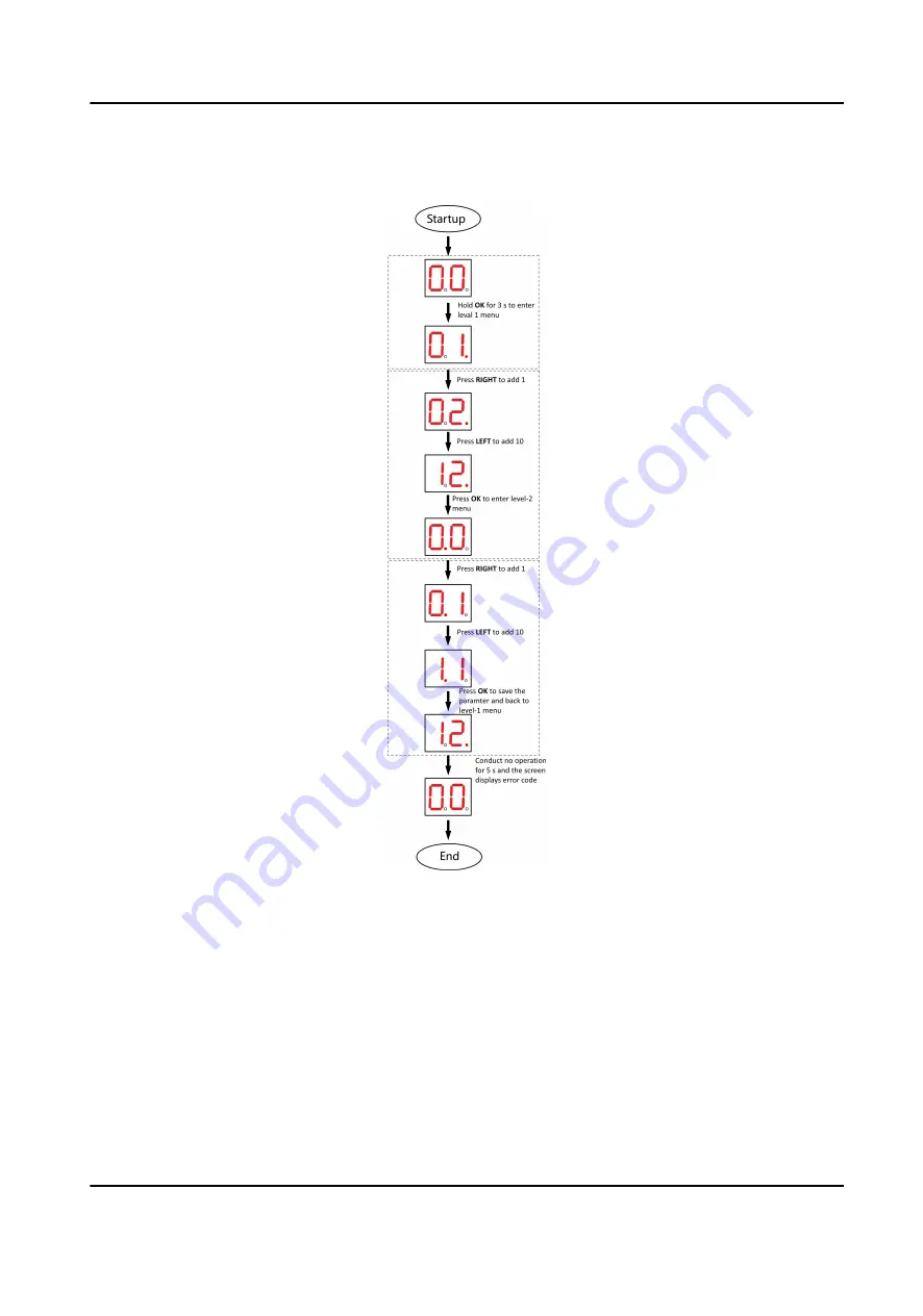
Button Configuration Procedure

Figure 5-2 Procedure

Steps:
1. Enter the configuration mode. The number of 1 will show up on the right side of the screen and

the device is ready for configuration.

2. Press LEFT and RIGHT to set the configuration No. Press OK to enter the level-2 menu and view

the parameters. Press CANCEL, or conduct no operation for 5 s to cancel configuration.

3. Press LEFT and RIGHT to set the parameters at your needs. Press OK to save the changes or

press CANCEL back to configuration No. setting without saving changes. Conduct no operations

for 5 s to cancel configuration.

DS-K3G411LX Series Tripod Turnstile User Manual

14

Summary of Contents for DS-K3G411LX Series

Page 1: ...DS K3G411LX Series Tripod Turnstile User Manual...

Page 2: ...U IS AT YOUR OWN RISK IN NO EVENT WILL HIKVISION BE LIABLE TO YOU FOR ANY SPECIAL CONSEQUENTIAL INCIDENTAL OR INDIRECT DAMAGES INCLUDING AMONG OTHERS DAMAGES FOR LOSS OF BUSINESS PROFITS BUSINESS INTE...

Page 3: ...by design principles For example for device with facial recognition features biometrics data is stored in your device with encryption method for fingerprint device only fingerprint template will be s...

Page 4: ...interference 2 This device must accept any interference received including interference that may cause undesired operation EU Conformity Statement This product and if applicable the supplied accessori...

Page 5: ...ge et 2 l utilisateur de l appareil doit accepter tout brouillage radio lectrique subi m me si le brouillage est susceptible d en compromettre le fonctionnement COMPLIANCE NOTICE The thermal series pr...

Page 6: ...wer source during servicing Keep body parts away from motors Disconnect the power source during servicing To prevent possible hearing damage do not listen at high volume levels for long periods All th...

Page 7: ...ith or generates direct current No naked flame sources such as lighted candles should be placed on the equipment This equipment is suitable for mounting on concrete or other non combustible surface on...

Page 8: ...he device cover Please use a soft and dry cloth when clean inside and outside surfaces of the device cover do not use alkaline detergents Please keep all wrappers after unpack them for future use In c...

Page 9: ...Available Models Product Name Model Tripod Turnstile DS K3G411LX DS K3G411LX Series Tripod Turnstile User Manual viii...

Page 10: ...Supply 8 4 3 Terminal Description 10 4 3 1 Lane Control Board Terminal Description 10 4 3 2 General Wiring 10 Chapter 5 Device Settings via Button 12 5 1 Configuration via Button 13 5 2 Pair Keyfob vi...

Page 11: ...ode selectable Bidirectional Entering Exiting lane The barrier opening and closing speed can be configured according to the visitor flow Self detection Self diagnostics and automatic alarm Remote cont...

Page 12: ...does not pass through the lane within the valid passing duration Up to 3000 visitor cards and up to 60 000 cards except for visitor cards can be added Up to 180 000 presenting card events can be recor...

Page 13: ...1 Hole Position Diagram 4 Bury cables Each lane buries 1 network cable and 1 high voltage cable For details see the system wiring diagram above Note The suggested inner diameter of the low voltage con...

Page 14: ...key to open the pedestals View the pictures below to find the lock holes Figure 3 1 Lock Holes 3 2 Install Pedestals Before You Start Prepare for the installation tools check the device and the access...

Page 15: ...rfaces If the installation area is too close to the wall make sure the distance between the pedestal with or without face recognition terminal and the wall should be more than 20 mm or the surface may...

Page 16: ...m entering Note Make sure the installation holes on the pedestals and the base are aligned with each other 5 Secure the pedestals with expansion bolts Note Do not immerse the pedestal in the water In...

Page 17: ...supports wiring the AC electric supply for the whole system s power supply Note The voltage fluctuation of the electric supply is between 100 VAC and 240 VAC 50 to 60 Hz The picture displayed below de...

Page 18: ...erminal N Blue are on the switch while terminal PE should connect to a ground wire yellow and green wire For product with switching power supply the wiring diagram is as follows For product with switc...

Page 19: ...ap at the end of the bare cable Make sure there s no bare copper or cable after the wiring The Terminal L and the Terminal N cannot be wired reversely Do not wire the input and output terminal reverse...

Page 20: ...Description The picture displayed below is the main control board diagram 4 3 2 General Wiring The general peripheral wiring of the lane control board Figure 4 2 General Wiring of Pedestal with Power...

Page 21: ...xit button use the same grounding interface Gate opens at the entrance exit connect to BTN1 BTN2 and GND The two 12 V power output interfaces are the power supply for face recognition terminals which...

Page 22: ...button Volume Adjustment Configure via button Authenticated Passing Not support Invalid Card No Not support Unmatched Fingerprint Not support Reverse Intrusion Configure via button Passing Timeout Co...

Page 23: ...ata CANCEL Return to the level 1 menu or exit the configuration from the level 1 menu OK Confirm the data or enter configuration mode or enter the submenu Note Configuration data is displayed by two d...

Page 24: ...set the configuration No Press OK to enter the level 2 menu and view the parameters Press CANCEL or conduct no operation for 5 s to cancel configuration 3 Press LEFT and RIGHT to set the parameters at...

Page 25: ...s user manual 1 Enter the keyfob pairing mode 1 Enter the configuration mode 2 Set the configuration No in Level 1 to 2 The device will enter the keyfob pairing mode 3 Set the configuration No in the...

Page 26: ...ance under control exit prohibited 3 Entrance under control exit on free passing mode 4 Both sides on free passing mode 5 Entrance on free passing mode exit under control 6 Entrance on free passing mo...

Page 27: ...nable to change 26 Reverse Passing 1 1 Disable 2 Enable 27 Exceeding Passing Duration 1 1 Disable 2 Enable 31 Unauthorized Passing 1 1 Disable 2 Enable Unable to change 32 Exceeding Authentication Dur...

Page 28: ...ption Default Value Parameters Notes 43 Fire Protection Type 2 1 Remain Closed 2 Remain Open 99 Restore to Default 1 1 Default 2 Start The device will reboot DS K3G411LX Series Tripod Turnstile User M...

Page 29: ...Appendix B Event and Alarm Type Event Alarm Type Passing Timeout None DS K3G411LX Series Tripod Turnstile User Manual 19...

Page 30: ...ent Index Content 1 Authenticated 2 Card No does not exist 3 Card No and fingerprint mismatch 4 Passing timeout 5 No permissions 6 Authentication time out 7 Authentication failed 8 Expired card DS K3G...

Page 31: ...Hikvision access control and video intercom devices Figure D 1 QR Code of Communication Matrix Device Command Scan the following QR code to get the device common serial port commands Note that the com...

Page 32: ...UD30763B...

Reviews: