HIKVISION DS-AT1000S Series Quick Start Manual Download Page 15

DS-AT1000S Series Storage System Quick Start Guide 

14 

2.2.2 Install HDD 

Selecting HDD Model 

It is recommended to adopt the certificated professional HDD models so as to ensure the stable 
running of the system and the reliable data storage. You are recommended to use the HDD in 
recommended HDD list. Please contact our technical support for the recommended HDD list. 


In order to avoid damages during transportation, it is recommended to package and transport the 
hard disks separately with the chassis of network storage system. 

Installing HDD 

Follow the steps below to install HDDs. 

Step 1


Remove the front panel cover. 

1)


Unlock the front panel cover with delivered key. 

2)


Hold the cover and pull it out till it gets out of the control of the lock. 

3)


Move the cover to right to remove it from front panel. 

Step 2


Press the


spring lock of the HDD on the left, drag the handle and then pull out the dummy 

HDD from the chassis along the guide rail. 
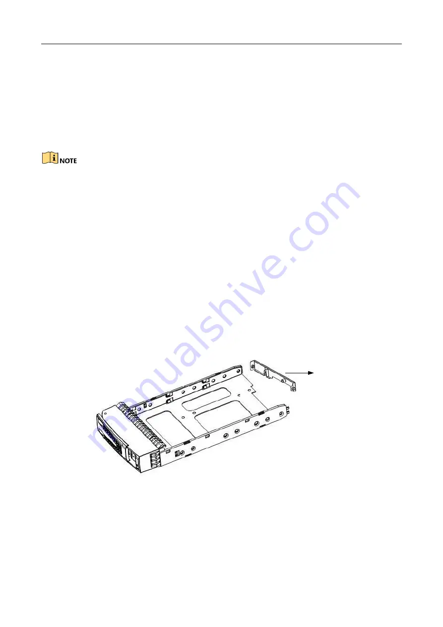
Step 3


(Optional) Remove the baffle, if any, from the dummy HDD. 

Baffle


Figure 2-11


Remove Baffle 

Step 4


Use four screws to secure the HDD (with the PCB side downward) to the bracket. In order to 
ensure the HDD pin holds the line with the rear of the plate, mount screws to the specific 
screw hole as shown. 

Summary of Contents for DS-AT1000S Series

Page 1: ...DS AT1000S Series Storage System Quick Start Guide...

Page 2: ...Front Panel 9 2 1 4 Rear Panel 11 2 2 Install Accessories 13 2 2 1 Installation Requirement 13 2 2 2 Install HDD 14 2 3 Startup 16 2 4 Shutdown 17 Chapter 3 Function Configuration 18 Chapter 4 Networ...

Page 3: ...s and logos mentioned below are the properties of their respective owners Legal Disclaimer TO THE MAXIMUM EXTENT PERMITTED BY APPLICABLE LAW THE PRODUCT DESCRIBED WITH ITS HARDWARE SOFTWARE AND FIRMWA...

Page 4: ...ce must accept any interference received including interference that may cause undesired operation EU Conformity Statement This product and if applicable the supplied accessories too are marked with C...

Page 5: ...000S 480 Symbol Conventions The symbols that may be found in this document are defined as follows Symbol Description Provides additional information to emphasize or supplement important points of the...

Page 6: ...e neutral line and GND line connections correct and the voltage between them must be less than 1 V Grounding for AC power supply system ensure the GND line is properly connected The grounding for the...

Page 7: ...ble to keep out the wind and sand Transportation Pack the equipment into the package Do not transport via open truck or open warehouse And do not transport the equipment with inflammable explosive and...

Page 8: ...stent to prevent the damage caused by a huge temperature difference If the device has been transported and stored for more than 10 days perform the previous operation and then start up and run the dev...

Page 9: ...View of DS AT1000S 360 DS AT1000S 440 and DS AT1000S 480 Figure 2 2 Overall View of DS AT1000S 160 DS AT1000S 240 DS AT1000S 300 and DS AT1000S 320 2 1 2 Front Panel The disk slots view of the device...

Page 10: ...AT1000S 300 and DS AT1000S 320 2 1 3 Description of Buttons in Front Panel DS AT1000S 360 DS AT1000S 440 and DS AT1000S 480 Figure 2 5 Front Panel Buttons Figure 2 6 Button Description Button Name Des...

Page 11: ...e button and alarm indicator When an alarm is triggered the indicator flashes in red and buzzer beeps Press the button to stop beeping Power indicator for controller A When controller A is connected a...

Page 12: ...least 4s and not more than 15s to turn off the system The indicator shows green when the system is running Positioning button and indicator Press this button or click Positioning on GUI to trigger lo...

Page 13: ...COM interface 9 Data network interface 3 3 Two USB interfaces 10 Management network interface 4 Two USB interfaces 11 Power module 2 5 Data network interface 1 12 IPMI 6 Data network interface 2 13 D...

Page 14: ...wing objects are in the package Storage system Power cord Gigabit Ethernet cable Delivered CD Screw package The following accessories are optional or user provided Gigabit Ethernet switch Rack guide r...

Page 15: ...system Installing HDD Follow the steps below to install HDDs Step 1 Remove the front panel cover 1 Unlock the front panel cover with delivered key 2 Hold the cover and pull it out till it gets out of...

Page 16: ...uide apparatus to the bottom Then press the securing handle to ensure the bracket has been seated into position and lock it Step 6 Repeat the operating steps above till all HDDs have been installed In...

Page 17: ...ill spinning at a high speed just after powering off unplugging the hard disk immediately will damage the discs The system supports HDD hot swapping yet the data storage safety is not ensured Please a...

Page 18: ...ton after startup or device will be forced to shut down and may course the data loss 2 4 Shutdown Step 1 Log in the storage system via Internet Explore For details refer to 4 1 Activate Storage System...

Page 19: ...parameters For details refer to 4 2 Configure Network Parameters Step 2 Operate quick configuration For details refer to 5 1 One Key Configuration Step 3 Format storage space For details refer to 5 2...

Page 20: ...stem Default IP address of management network interface is 10 254 254 254 Step 3 Visit https 10 254 254 254 2004 in web browser to access the storage system Step 4 Create password for storage system a...

Page 21: ...default network interface 1 and 4 are bonded as a data network interface bond network interface 1 and bonding mode is XOR DS AT1000S 160 DS AT1000S 240 DS AT1000S 300 and DS AT1000S 320 series storage...

Page 22: ...e to view the IP address Default IP address of management network interface is 10 254 254 254 4 2 2 Modify IP Address of Bond Network Interface Step 1 Go to Device Information Modify Network Step 2 Cl...

Page 23: ...system requires at least 16 HDDs DS AT1000S 360 storage system requires at least 18 HDDs DS AT1000S 440 storage system requires at least 22 HDDs DS AT1000S 480 storage system requires at least 24 HDD...

Page 24: ...configuration finishes Figure 5 2 Prompt 5 2 Format Storage Space 5 2 1 Activate Hybrid SAN Sub System Purpose You can only use Internet Explorer 8 0 and above to visit Hybrid SAN sub system Step 1 Vi...

Page 25: ...pecial characters in order to increase the security of your product And we recommend you reset your password regularly especially in the high security system resetting the password monthly or weekly c...

Page 26: ...ic parameters 6 1 Camera Management Step 1 Log in to Hybrid SAN sub system For details refer to 5 2 1 Activate Hybrid SAN Sub System Step 2 Go to Configuration System Camera Management Figure 6 1 Came...

Page 27: ...as to add and click OK Network cameras of the same password with the storage system will be successfully added 6 2 Configure Recording Schedule Purpose By default network cameras start continuous reco...

Page 28: ...e 27 6 3 Live View Go to Live View You can preview live images start manual recording capture pictures turn on live view audio etc Figure 6 4 Live View 6 4 Playback Go to Playback You can play back se...

Page 29: ...UD28605B...

Reviews: