background image


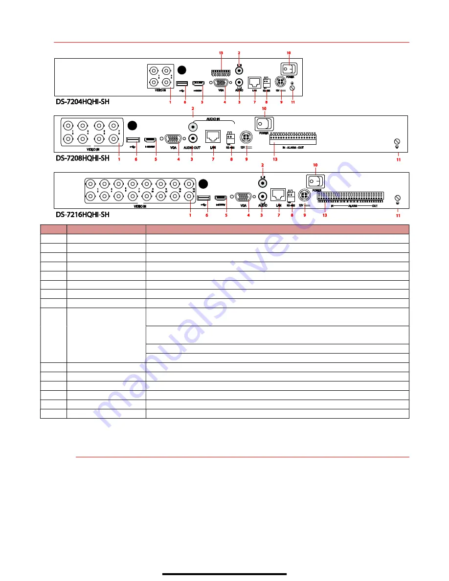
 R E A R   P A N E L S  


No. 

Item 

Description 

Video In 

BNC interface for TVI and analog video input 

Video Out 

BNC connector for spot output/video output 

Audio In 

RCA connector 

USB Port 

USB port for additional devices. 

HDMI 

HDMI video output connector 

VGA 

DB-15 connector for VGA output. Display local video output and menu. 

Audio Out 

RCA connector 

Network Interface 

Connector for network 

RS-485 Interface 

Connector for RS-485 devices. T+ and T- pins connect to R+ and R- pins of PTZ 

receiver respectively. 

D+, D- pin connects to Ta, Tb pin of controller. For cascading devices, the first 

DVR’s D+, D- pin should be connected with the D+, D- pin of the next DVR. 

Connector for alarm input 

Connector for alarm output 

10 

Power Supply 

12 VDC power supply 

11 

Power Switch 

Switch for turning the device on/off   

12 

Gnd 

Ground 

13 

Line In 

BNC connector for audio input 

14 

eSATA 

Connects external SATA HDD, CD/DVD-RW 

15 

RS-232 Interface 

Connector for RS-232 devices 

  1 

C O N N E C T   D E V I C E S  


1.


Connect power supply cord to the DVR and plug into 110 VAC outlet (surge suppressor is 

recommended). 

2.


Connect DVR to LAN using Cat 5e (or better) cable. 

3.


Connect video monitor(s) to DVR using HDMI and/or VGA cables, as appropriate. 

4.


Connect mouse to USB port. 

5.


Connect to audio I/O using RCA connectors. 

Summary of Contents for DS-7204HGHI-SH

Page 1: ...he supplied accessories too are marked with CE and comply therefore with the applicable harmonized European standards listed under the EMC Directive 2004 108 EC the RoHS Directive 2011 65 EU 2012 19 EU WEEE Directive Products marked with this symbol cannot be disposed of as unsorted municipal waste in the European Union For proper recycling return this product to your local supplier upon the purch...

Page 2: ... M E N U T R E E Use this menu tree to navigate the embedded menus F R O N T P A NE L 1 Status Indicators Power Illuminates when rear panel power switch is turned on Status Blinks when data is being read from or written to HDD TX RX Blinks when network connection is functioning properly 2 IR Receiver Receiver for IR remote 3 USB Port Connects USB mouse or USB flash memory devices ...

Page 3: ... pin of controller For cascading devices the first DVR s D D pin should be connected with the D D pin of the next DVR Connector for alarm input Connector for alarm output 10 Power Supply 12 VDC power supply 11 Power Switch Switch for turning the device on off 12 Gnd Ground 13 Line In BNC connector for audio input 14 eSATA Connects external SATA HDD CD DVD RW 15 RS 232 Interface Connector for RS 23...

Page 4: ...ters At least two types of the above mentioned characters are required Risky passwords as determined by the system are not allowed Also reset password regularly 3 Click OK to save password and activate device Log In 1 User Name field will be prefilled with admin 2 Input Password default wrong password 7 x locks account for 30 minutes can be changed in setup 3 Click OK 4 F O R M A T T H E H A R D D...

Page 5: ...work connection is required to access the cameras remotely 1 Go to MENU SYSTEM CONFIGURATION NETWORK 2 Enable DHCP check the checkbox 3 Press Refresh button to update the IPv4 address subnet mask and IPv4 default gateway DATE TIME Date and time settings TIME ZONE Time zone and daylight savings time settings ENABLE NTP Network Time Protocol settings HDD LIST TOTAL HDD SPACE FREE SPACE ...

Page 6: ...ORT is responsible for the mobile app and client software log in HTTP PORT is responsible for Web browser log in RTSP PORT is responsible for video audio streaming NOTE The HTTP port server port and RTSP can be changed to avoid conflicts with the ISP or if multiple devices are installed at a single location GENERAL TAB Select this tab NIC TYPE Not changeable ENABLE DHCP Check box so that router wi...

Page 7: ... connect com If not check the Custom checkbox and type dev hik connect com 4 Click the Apply button Status will change to Online if all settings are correct 5 Note the Serial Number and Verification Code shown here for use when registering the DVR in your Hik Connect account or use the QR code displayed 2 To see a device s video stream on the Hik Connect or iVMS 4500 mobile app add the device 1 Lo...

Page 8: ...nation Edit basic camera parameters Add the detected IP camera Camera is disconnected click icon for camera s exception information Delete the IP camera Play camera s live video Advanced camera settings Upgrade the connected camera Security Show active inactive camera security status or the password strength 10A D D A N A L O G C A ME R A S Adding Analog Cameras 1 Connect analog camera s to the Vi...

Page 9: ... Icons in the upper right of screen show each camera s record and alarm status Alarm video loss tampering motion detection sensor alarm or VCA alarm Record manual record continuous record motion detection alarm or VCA triggered record Event Exception event and exception information appears at lower left corner of screen COLOR Shows Recording Schedule Blue Continuous Yellow Event motion alarm Grey ...

Page 10: ...set the motion detection for each camera In this step the Copy option is only for analog cameras IP cameras need to be configured individually 7 Go to RECORDING CONFIGURATION RECORD QUALITY and set the following items Stream Type enables disables audio streaming from the cameras if the camera does not have audio capabilities Stream Type will have only Video option Resolution sets recording resolut...

Page 11: ... microphone or only analog channels 1 4 Video Stream changes recording between Main Stream and Sub Stream requires restart Recommended Recording Parameters Resolution Video Quality Frame Rate fps Bitrate Kbps 320 x 240 QVGA Medium 3 squares 12 15 207 352 x 240 CIF 384 640 x 480 VGA 768 704 x 480 4CIF 1024 1280 x 720 720p 2048 1280 x 960 960p 2048 1600 x 1200 2 MP 2560 1920 x 1080 1080p 3072 2048 x...

Page 12: ...ick the button in the shortcut operation menu Only files recorded in the past five minutes will be played SUBSTREAM TAB Select CAMERA Select camera STREAM TYPE Select choice RESOLUTION Can go up only to 4CIF VIDEO QUALITY Select number of green squares to set quality in example sensitivity is set to 3 SUBSTREAM TAB SMART SEARCH PLAYBACK Search for specific defined activities FULL SCREEN Goes to fu...

Page 13: ...USB port 1 Go to MENU PLAYBACK 2 Select the date and beginning time of the incident 3 Click START CLIPPING button 4 Select the ending time of the incident 5 Click END CLIPPING same button as START CLIPPING Clip will be marked 6 Repeat steps 1 6 as many times as required 7 Click FILE MANAGEMENT to display a new window containing all marked clips 8 Select the desired clips 9 Click EXPORT CAMERA LIST...

Page 14: ...t 2 In the Video Export interface choose camera s to back up and click Quick Export button 3 Choose backup device USB flash drive USB HDD or DVD writer 4 Click Export to check backup choose recorded file in Export interface and click button CLIP LIST Select desired clips multiple clips selected from same camera will be stitched together EXPORT Save clips to USB device ...

Page 15: ...nada Inc 4848 Levy Street St Laurent Quebec Canada H4R 2P9 Telephone 1 909 895 0400 Toll Free in USA 1 866 200 6690 E Mail sales usa hikvision com www hikvision com 2017 Hikvision USA Inc All Rights Reserved Specifications subject to change without notice QSG DS 72xxHGHI SH 042817NA ...

Reviews: