HIKVISION DS-3T1306P-SI/HS Quick Start Manual Download Page 9


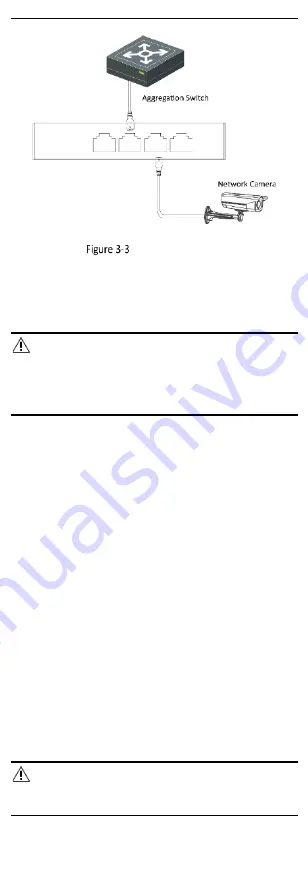
RJ45 Port Connection 

3.3


Connect SFP Optical Module 

Connecting  an  SFP  optical  module  is  supported  when  the  device 
has a fiber optical port. 

Steps 

Caution 


Single-Mode optical module needs to be paired for use. 


Do not bend an optical fiber (curvature radius ≥ 10 cm) overly. 


Do not look  directly at  an optical fiber connector because the 
laser generated is harmful to eyes. 

1.


Connect the two paired SFP optical modules with an optical fiber. 

2.


Hold the SFP optical module from one side, and smoothly plug it 
into the device along the SFP port slot until the optical module 
and the device are closely attached. 

3.


After powering on the device, check the status of the optical port 
indicator. 

-


If the indicator is lit, the link is connected. 

-


If the indicator is unlit, the link is disconnected. 

4.


Check  the  line,  and  make  sure  that  the  peer  device  has  been 
enabled. 


Device Powering-On 

Please use the attached power adapter or power cord to power on 
the  device. If no power adapter or power cord is  provided in the 
package, please use a qualified one to power on the device. 

Before powering on your device, make sure that: 


The  operating  power  supply  is  compliant  with  rated  input 
standard. 


Port cables and grounding cables are correctly connected. 


If  there  is  outdoor  cabling,  connect  a  lightning  rod  and  a 
lightening arrester to the cable. 

Caution 

PoE power supply lines and strong current wires cannot be wired 
together, otherwise PDs or switch ports will be burnt. 

Summary of Contents for DS-3T1306P-SI/HS

Page 1: ...Smart Managed Industrial PoE Switch Quick Start Guide UD27785B A...

Page 2: ...d via the PoE port have their shells protected and fire proofed because the switches are not compliant with the Limited Power Source LPS standard In the use of the product you must be in strict compli...

Page 3: ...rs table cloths curtains etc The openings shall never be blocked by placing the device on a bed sofa rug or other similar surface No naked flame sources such as lighted candles should be placed on the...

Page 4: ...esign meets the requirements of networking application in multiple scenes with excellent electromagnetic compatibility and shock protection capability 1 2 Packing List Accessory Quantity Switch 1 Powe...

Page 5: ...y Unlit No power supply is connected or power supply is abnormal 4 G2 Port Indicator Solid on The gigabit SFP fiber optical port is connected Flashing The gigabit SFP fiber optical port is transmittin...

Page 6: ...ge prepare them yourself Before You Start Ensure that the desktop wall rack or rail is stable and firm enough Keep the room well ventilated Leave at least 10 cm of heat dissipation space around the de...

Page 7: ...evice Fix Brackets to Rack 2 4Rail Mounted Installation Steps 1 Fix the clip to the device Insert the end of the DIN rail mounted unit into the notch under the clip Rail Mounted Installation 2 Press t...

Page 8: ...Grounding with Grounding Bar 3 1 2 Without Grounding Bar If there is no grounding bar but the earth is nearby and the grounding body is allowed to be buried follow the steps below Steps 1 Bury an angl...

Page 9: ...the device check the status of the optical port indicator If the indicator is lit the link is connected If the indicator is unlit the link is disconnected 4 Check the line and make sure that the peer...

Page 10: ...e you are required to create a password for the device s administrator user admin to activate the device before it can be added to the software and work properly The device can be activated through SA...

Page 11: ...S 4200 Client After the device is activated you need to modify the device IP address to make sure that it is in the same network segment with that of the PC running the client before adding it to the...

Page 12: ...ptional Check Synchronize Time to synchronize the device time with that of the PC running the client after adding the device to the client 6 Click Add to add the device to the client Note It is recomm...

Page 13: ...a device by scanning the QR code generated by iVMS 4200 or web Before You Start Make sure that the device you are going to use is connected to a network Steps 1 Tap 2 Scan the QR code of the device to...

Page 14: ...vice serial No device model device type and so on Generate Device QR Code If a device is added by scanning the QR code generated by iVMS 4200 or web you can generate a QR code of the device If you do...

Page 15: ...e iVMS 4200 client The device verification code operation code can be obtained in Hik Connect Settings on the iVMS 4200 client 4 Tap Add to Site and select a site for the device 5 Tap Add to add the d...

Page 16: ...13 User Manual Web User Manual and Client User Manual Hik ProConnect App Android iOS Note The Hik ProConnect user manual is available for your reference on the app...

Reviews: