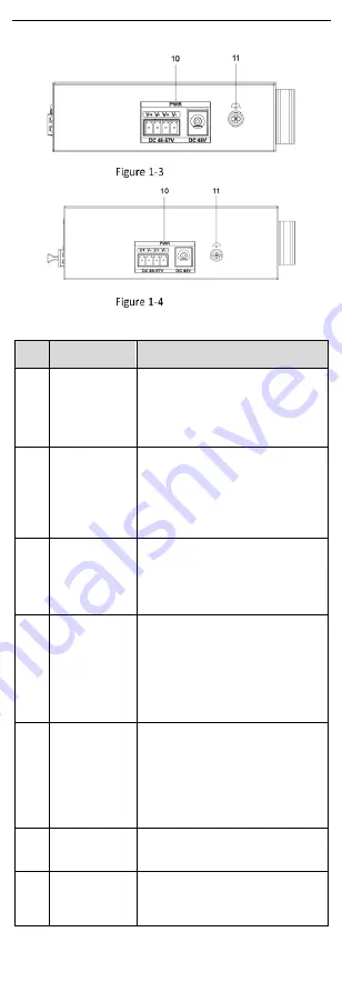
HIKVISION DS-3T1306P-SI/HS Quick Start Manual Download Page 5


Right Panel 


1306P Series 


1310P Series 

Port/Indicator Description 

No. 

Indicator/Port 

Description 

1


LINK/ACT 
Indicator


Solid on: The port is connected. 


Flashing: The  port is  transmitting 
data. 


Unlit: The port is disconnected or 
connection is abnormal.


2


PoE Indicator


Solid  on:  The  switch  supplies 
power  to  a  powered  device  (PD) 
normally.   


Unlit:  The  switch  is  disconnected 
from  a  PD  or  power  supply  is 
abnormal.


3


PWR Indicator


Solid  on:  The  switch  is  powered 
on normally. 


Unlit:  No  power  supply  is 
connected  or  power  supply  is 
abnormal.


G2 Port 
Indicator 


Solid  on:  The  gigabit  SFP  fiber 
optical port is connected.   


Flashing:  The  gigabit  SFP  fiber 
optical port is transmitting data.   


Unlit: The gigabit SFP fiber optical 
port 

is 

disconnected 

or 

connection is abnormal.


PoE-MAX 
Indicator 


Solid  on/Flashing:  The  output 
power  of  the  switch  is  about  to 
reach the upper limit. The power 
supply  may  be  abnormal  if  more 
devices are connected. 


Unlit:  The  switch  supplies  power 
to a PD normally.


100 Mbps PoE 
RJ45 Port 

Used  for  connection  to  a  PD  via  a 
network cable. 

Gigabit RJ45 
Port 

Used  for  connection  to  another 
device via a network cable.


Summary of Contents for DS-3T1306P-SI/HS

Page 1: ...Smart Managed Industrial PoE Switch Quick Start Guide UD27785B A...

Page 2: ...d via the PoE port have their shells protected and fire proofed because the switches are not compliant with the Limited Power Source LPS standard In the use of the product you must be in strict compli...

Page 3: ...rs table cloths curtains etc The openings shall never be blocked by placing the device on a bed sofa rug or other similar surface No naked flame sources such as lighted candles should be placed on the...

Page 4: ...esign meets the requirements of networking application in multiple scenes with excellent electromagnetic compatibility and shock protection capability 1 2 Packing List Accessory Quantity Switch 1 Powe...

Page 5: ...y Unlit No power supply is connected or power supply is abnormal 4 G2 Port Indicator Solid on The gigabit SFP fiber optical port is connected Flashing The gigabit SFP fiber optical port is transmittin...

Page 6: ...ge prepare them yourself Before You Start Ensure that the desktop wall rack or rail is stable and firm enough Keep the room well ventilated Leave at least 10 cm of heat dissipation space around the de...

Page 7: ...evice Fix Brackets to Rack 2 4Rail Mounted Installation Steps 1 Fix the clip to the device Insert the end of the DIN rail mounted unit into the notch under the clip Rail Mounted Installation 2 Press t...

Page 8: ...Grounding with Grounding Bar 3 1 2 Without Grounding Bar If there is no grounding bar but the earth is nearby and the grounding body is allowed to be buried follow the steps below Steps 1 Bury an angl...

Page 9: ...the device check the status of the optical port indicator If the indicator is lit the link is connected If the indicator is unlit the link is disconnected 4 Check the line and make sure that the peer...

Page 10: ...e you are required to create a password for the device s administrator user admin to activate the device before it can be added to the software and work properly The device can be activated through SA...

Page 11: ...S 4200 Client After the device is activated you need to modify the device IP address to make sure that it is in the same network segment with that of the PC running the client before adding it to the...

Page 12: ...ptional Check Synchronize Time to synchronize the device time with that of the PC running the client after adding the device to the client 6 Click Add to add the device to the client Note It is recomm...

Page 13: ...a device by scanning the QR code generated by iVMS 4200 or web Before You Start Make sure that the device you are going to use is connected to a network Steps 1 Tap 2 Scan the QR code of the device to...

Page 14: ...vice serial No device model device type and so on Generate Device QR Code If a device is added by scanning the QR code generated by iVMS 4200 or web you can generate a QR code of the device If you do...

Page 15: ...e iVMS 4200 client The device verification code operation code can be obtained in Hik Connect Settings on the iVMS 4200 client 4 Tap Add to Site and select a site for the device 5 Tap Add to add the d...

Page 16: ...13 User Manual Web User Manual and Client User Manual Hik ProConnect App Android iOS Note The Hik ProConnect user manual is available for your reference on the app...

Reviews: