background image

Thermal Network Camera User Manual 

Chapter 3 Temperature Measurement 

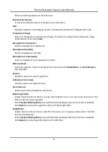
When you enable this function, the device measures the actual temperature of the scene. It 
alarms when temperature exceeds the temperature threshold value. 

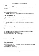
3.1 Notice 

This part introduces the notices of configuring temperature measurement function. 


The target surface should be as vertical to the optical axis as possible. It is recommended that 
the angle of oblique image plane should be less than 45°. 


The target image pixels should be more than 5 × 5. 


Please select line thermography or area thermography for a certain area temperature 
measurement. The point thermography is not recommended in case of deviation occurred 
during device movement to affect the accuracy of temperature measurement. 

Summary of Contents for DS-2TD2137T-7/P

Page 1: ...Thermal Network Camera User Manual ...

Page 2: ... BY YOU IS AT YOUR OWN RISK IN NO EVENT WILL HIKVISION BE LIABLE TO YOU FOR ANY SPECIAL CONSEQUENTIAL INCIDENTAL OR INDIRECT DAMAGES INCLUDING AMONG OTHERS DAMAGES FOR LOSS OF BUSINESS PROFITS BUSINESS INTERRUPTION OR LOSS OF DATA CORRUPTION OF SYSTEMS OR LOSS OF DOCUMENTATION WHETHER BASED ON BREACH OF CONTRACT TORT INCLUDING NEGLIGENCE PRODUCT LIABILITY OR OTHERWISE IN CONNECTION WITH THE USE OF...

Page 3: ... CHEMICAL OR BIOLOGICAL WEAPONS ANY ACTIVITIES IN THE CONTEXT RELATED TO ANY NUCLEAR EXPLOSIVE OR UNSAFE NUCLEAR FUEL CYCLE OR IN SUPPORT OF HUMAN RIGHTS ABUSES IN THE EVENT OF ANY CONFLICTS BETWEEN THIS MANUAL AND THE APPLICABLE LAW THE LATTER PREVAILS ...

Page 4: ...dicates a hazardous situation which if not avoided will or could result in death or serious injury Caution Indicates a potentially hazardous situation which if not avoided could result in equipment damage data loss performance degradation or unexpected results Note Provides additional information to emphasize or supplement important points of the main text ...

Page 5: ... is properly connected to the power socket The socket outlet shall be installed near the equipment and shall be easily accessible DO NOT connect multiple devices to one power adapter to avoid over heating or fire hazards caused by overload DO NOT touch the bare metal contacts of the inlets after the circuit breaker is turned off Electricity still exists identifies the positive terminal s of equipm...

Page 6: ...hen it is connected to the Internet Please contact us when the device might exist network security risks Please understand that you have the responsibility to configure all the passwords and other security settings about the device and keep your user name and password Maintenance If the product does not work properly please contact your dealer or the nearest service center We shall not assume any ...

Page 7: ... Emergency If smoke odor or noise arises from the device immediately turn off the power unplug the power cable and contact the service center COMPLIANCE NOTICE The thermal series products might be subject to export controls in various countries or regions including without limitation the United States European Union United Kingdom and or other member countries of the Wassenaar Arrangement Please c...

Page 8: ...3 2 Thermography Configuration Flow Chart 6 3 3 Automatic Thermography 8 3 3 1 Set Thermography Parameters 8 3 3 2 Set Normal Mode 10 3 3 3 Set Expert Mode 11 3 3 4 Set Thermography Rule 11 3 3 5 Point Thermography 13 3 3 6 Line Thermography 13 3 3 7 Area Thermography 13 3 4 Set Shielded Region 13 3 5 Manual Thermography 14 Chapter 4 Fire Source Detection 15 4 1 Recommended Scene 15 4 2 Set Fire D...

Page 9: ...Detect Audio Exception 27 Chapter 7 Arming Schedule and Alarm Linkage 29 7 1 Set Arming Schedule 29 7 2 Linkage Method Settings 29 7 2 1 Trigger Alarm Output 29 7 2 2 FTP NAS Memory Card Uploading 30 7 2 3 Send Email 31 7 2 4 Notify Surveillance Center 32 7 2 5 Trigger Recording 32 7 2 6 Set Audible Alarm Output 32 7 2 7 Set Flashing Alarm Light Output 33 Chapter 8 Live View 34 8 1 Live View Param...

Page 10: ... Bitrate 38 9 1 5 Video Quality 39 9 1 6 Frame Rate 39 9 1 7 Video Encoding 39 9 1 8 Smoothing 40 9 1 9 Display VCA Info 40 9 1 10 Audio Settings 41 9 1 11 Two way Audio 41 9 1 12 Set ROI 42 9 2 Display Settings 42 9 2 1 Image Adjustment Thermal Channel 42 9 2 2 DNR 43 9 2 3 Set Palette 43 9 2 4 Set Target Color 44 9 2 5 DDE 44 9 2 6 Brightness Sudden Change 44 9 2 7 Enhance Regional Image 44 9 2 ...

Page 11: ...d Download Video 52 10 3 Capture Configuration 53 10 3 1 Capture Automatically 53 10 3 2 Capture Manually 53 10 3 3 View and Download Picture 54 Chapter 11 Network Settings 55 11 1 TCP IP 55 11 1 1 Multicast Discovery 56 11 2 Port 56 11 3 Port Mapping 57 11 3 1 Set Auto Port Mapping 57 11 3 2 Set Manual Port Mapping 58 11 4 Multicast 58 11 5 SNMP 58 11 6 Access to Device via Domain Name 59 11 7 Ac...

Page 12: ... Export Configuration File 65 12 4 Export Diagnose Information 66 12 5 Reboot 66 12 6 Restore and Default 66 12 7 Upgrade 66 12 8 View Open Source Software License 67 12 9 Time and Date 67 12 9 1 Synchronize Time Manually 67 12 9 2 Set NTP Server 67 12 9 3 Set DST 68 12 10 Set RS 232 68 12 11 Set RS 485 68 12 12 Set Same Unit 69 12 13 Security 69 12 13 1 Authentication 69 12 13 2 Security Audit Lo...

Page 13: ...8 Set QoS 74 12 13 9 Set IEEE 802 1X 74 12 14 User and Account 74 12 14 1 Set User Account and Permission 74 Chapter 13 Appendix 76 13 1 Common Material Emissivity Reference 76 13 2 Device Command 76 13 3 Device Communication Matrix 77 13 4 FAQ 77 ...

Page 14: ...stem helps you discover unexpected events immediately and protects your property 1 2 Function This section introduces main functions of the device Note Not all models support the configurations below Take the actual product for reference Fire Detection Device can detect the dynamic fire source in the scene and output pre alarm and alarm to protect the property Temperature Measurement Device can me...

Page 15: ...e list and select Inactive device 4 Create and input the new password in the password field and confirm the password Caution We highly recommend you create a strong password of your own choosing using a minimum of 8 characters including upper case letters lower case letters numbers and special characters in order to increase the security of your product And we recommend you reset your password reg...

Page 16: ...g the password monthly or weekly can better protect your product 5 Click OK 6 Input the activation password to log in to the device 7 Optional Go to Configuration Network Basic TCP IP to change the IP address of the device to the same segment of your network 2 3 Login Log in to the device via Web browser 2 3 1 Plug in Installation Certain operation systems and web browser may restrict the display ...

Page 17: ...ation of certain functions are restricted For example Playback and Picture are not available For detailed restricted function refer to the actual device Note The device only supports Windows and Mac OS system and does not support Linux system 2 3 2 Illegal Login Lock It helps to improve the security when accessing the device via Internet Go to Configuration System Security Security Service and ena...

Page 18: ...uring temperature measurement function The target surface should be as vertical to the optical axis as possible It is recommended that the angle of oblique image plane should be less than 45 The target image pixels should be more than 5 5 Please select line thermography or area thermography for a certain area temperature measurement The point thermography is not recommended in case of deviation oc...

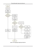
Page 19: ...Thermal Network Camera User Manual 6 3 2 Thermography Configuration Flow Chart This part introduces the process of configuring temperature measurement ...

Page 20: ...Thermal Network Camera User Manual 7 Figure 3 1 Thermography Configuration Flow Chart ...

Page 21: ...Click Save 3 Go to Configuration Temperature Measurement Basic Settings to configure parameters Enable Temperature Measurement Check to enable temperature measurement function Enable Color Temperature Check to display Temperature Color Ruler in live view Display Temperature Info on Stream Check to display temperature information on the stream Display Max Min Average Temperature Check to display ma...

Page 22: ...urement Fixed Distance and Self Adaption are selectable Version View the version of current algorithm Calibration File Version View the version of calibration file Alarm Interval Set the alarm interval between two alarms Reflect Light Filter Enable these functions if there is strong reflect light from sun or it may cause false alarm The filter sensitivity can be adjusted Check Display Filtering St...

Page 23: ...target The emissivity of each object is different Distance The distance between the target and the device Pre Alarm Threshold When the temperature of target exceeds the pre alarm threshold and this status keeps more than Filtering Time it triggers pre alarm Alarm Threshold When the temperature of target exceeds the alarm threshold and this status keeps more than Filtering Time it triggers alarm Pr...

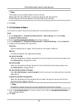
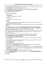
Page 24: ...Optional Click Area s Temperature Comparison to set the alarm rules and the temperature 6 Refer to Set Arming Schedule for setting scheduled time Refer to Linkage Method Settings for setting linkage method 7 Click Save The maximum temperature and thermography rules will be displayed on the live view Note Go to Image VCA Rules Display to adjust the fonts size and the temperature color of normal ala...

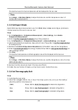
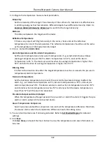
Page 25: ... and alarms when its average temperature is higher than 55 C Filtering Time It refers to the duration time after the target temperature reaches or exceeds the pre alarm temperature alarm temperature Tolerance Temperature Set the tolerance temperature to prevent the constant temperature change to affect the alarm E g set tolerance temperature as 3 C set alarm temperature as 55 C and set pre alarm t...

Page 26: ...t the length Go to Live View interface to view the maximum temperature and rule of the line in thermal channel 3 3 7 Area Thermography Configure the temperature measurement rule and monitor the maximum temperature of the area Steps 1 Click and drag the mouse in the liveview to draw the area and right click to finish drawing 2 Click and move the area to adjust the position 3 Drag the corners of the...

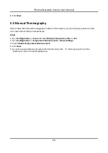
Page 27: ...n on the live view to show the real temperature Steps 1 Go toConfiguration Local and select Display Temperature Info as Yes 2 Go toConfiguration Temperature Measurement Basic Settings 3 Check Enable Temperature Measurement 4 Click Save 5 Go to live view interface and select thermal channel click Click any position on the interface to show the real temperature ...

Page 28: ...opriate scene Fire source detection can be applied to indoor and outdoor monitoring with a large maximum detection radius To achieve the best monitoring effect please set the installation place as requirements below The installation place should be the highest position within the detection area The lens should not be covered during movement to detect the maximum area It is better to choose the ins...

Page 29: ...d the fire source on stream when fire occurs 7 Optional you can shield certain areas from being detected in fire source detection 1 Go to Configuration Event Smart Event Fire Source Detection Shield 2 Check Enable Fire Source Detection Shield 3 Click Draw Area and drag the mouse in the live view to draw the area Release the mouse to finish drawing 4 You can drag the corners of the red rectangle ar...

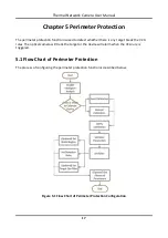
Page 30: ...whether there is any target break the VCA rules The optical camera will track the target or the device will alarm when the VCA rule is triggered 5 1 Flow Chart of Perimeter Protection The process of configuring the perimeter protection function is described below Figure 5 1 Flow Chart of Perimeter Protection Configuration ...

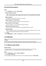
Page 31: ...elect to display the size information of the target on the alarm picture Snapshot Settings Select to upload the picture to the surveillance center when the VCA alarm occurs You can also set the quality and resolution of the picture separately 2 Click Save Go to Configuration Local check Enable rules to display rules information on the live view 5 3 Calibration Note Not all models support the calib...

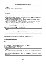
Page 32: ...an set the shielded area Refer to Set Shielded Region for detail settings 5 When the person exits click to stop calibration Note After auto calibration refer to Verify the Calibration Result to verify if the calibration is successful Set manual calibration if the auto calibration failed or the verified result turns bad Result After calibration the height and angle of camera will be shown in live v...

Page 33: ... function can verify whether the calibrated value is consistent with the actual value Steps 1 Click 2 Click and drag a vertical line in the view 3 Move the line to the target then click to caculate the length Compare the calculated line length to the actual length to verify the calibration settings 4 Click to exit Note Verify not only person but also other objects appeared in the view Such as car ...

Page 34: ...n the live view Right click the mouse to finish drawing 2 Set Duration When a target intrudes into the set area and stays in the area for more than the set duration the device triggers an intrusion alarm 3 Set Sensitivity The higher the value is the easier the target can be detected Region Entrance and Region Exit Click to draw an area in the live view Right click the mouse to finish drawing Targe...

Page 35: ...ncern the height of animal 6 Optional Repeat steps above to configure other rules 7 Optional Click to copy the same settings to other rules 8 Click Save 9 Optional you can shield certain areas from being detected Refer to Set Shielded Region for detailed settings 10 Set Arming Schedule and Linkage Method Settings for each rule 5 5 Advanced Configuration Go to Configuration VCA Advanced Configurati...

Page 36: ...tion Mode and set rule region and rule parameters For the information about normal mode see Normal Mode For the information about expert mode see Expert Mode 5 Set the arming schedule and linkage methods For the information about arming schedule settings see Set Arming Schedule For the information about linkage methods see Linkage Method Settings 6 Click Save 6 1 1 Normal Mode You can set motion d...

Page 37: ...ight switch is disabled Day Night Auto Switch The system switches day night mode automatically according to environment It displays colored image at day and black and white image at night Day Night Scheduled Switch The system switches day night mode according to the schedule It switches to day mode during the set periods and switches to night mode during the other periods Note This function is not...

Page 38: ...to set multiple areas 6 2 Set Video Tampering Alarm When the configured area is covered and cannot be monitored normally the alarm is triggered and the device takes certain alarm response actions Steps 1 Go to Configuration Event Basic Event Video Tampering 2 Check Enable 3 Set the Sensitivity The higher the value is the easier to detect the area covering 4 Click Draw Area and drag the mouse in th...

Page 39: ... the current device Before You Start Make sure the external alarm device is connected See Quick Start Guide for cables connection Steps 1 Go to Configuration Event Basic Event Alarm Input 2 Check Enable Alarm Input Handing 3 Select Alarm Input NO and Alarm Type from the dropdown list Edit the Alarm Name 4 Refer to Set Arming Schedule for setting scheduled time Refer to Linkage Method Settings for ...

Page 40: ...e abnormal sound in the scene such as the sudden increase decrease of the sound intensity and some certain actions can be taken as response Steps 1 Go to Configuration Event Smart Event Audio Exception Detection 2 Select one or several audio exception detection types Audio Loss Detection Detect sudden loss of audio track Sudden Increase of Sound Intensity Detection Detect sudden increase of sound ...

Page 41: ...ity Detection Detect sudden decrease of sound intensity Sensitivity is configurable 3 Refer to Set Arming Schedule for setting scheduled time Refer to Linkage Method Settings for setting linkage methods 4 Click Save Note The function varies according to different models ...

Page 42: ...d time period Drag the both ends to adjust the time period Click on the selected time period and drag it on the time bar 4 Optional Click Copy to to copy the same settings to other days 5 Click Save 7 2 Linkage Method Settings You can enable the linkage functions when an event or alarm occurs 7 2 1 Trigger Alarm Output If the device has been connected to an alarm output device and the alarm output...

Page 43: ... Set automatic alarm parameters Alarm Output No Select the alarm output No according to the alarm interface connected to the external alarm device Alarm Name Custom a name for the alarm output Delay It refers to the time duration that the alarm output remains after an alarm occurs 2 Set the alarming schedule For the information about the settings see Set Arming Schedule 3 Click Copy to to copy the...

Page 44: ...put your user name and password to log in to the server 3 Set the E mail Encryption When you select SSL or TLS and disable STARTTLS emails are sent after encrypted by SSL or TLS The SMTP port should be set as 465 When you select SSL or TLS and Enable STARTTLS emails are sent after encrypted by STARTTLS and the SMTP port should be set as 25 Note If you want to use STARTTLS make sure that the protoc...

Page 45: ...enter when an alarm event is detected 7 2 5 Trigger Recording Check Trigger Recording and the device records the video about the detected alarm event For recording settings refer to Video Recording and Picture Capture 7 2 6 Set Audible Alarm Output When the device detects targets in the detection area audible alarm can be triggered as a warning Steps 1 Go to Configuration Event Basic Event Audible...

Page 46: ...ption Flashing Alarm triggers the light to flash for a certain duration Set the flashing speed in Flashing Frequency Solid Alarm triggers the light to turn on for a certain duration 3 Set the light action duration and the brightness Flashing Duration The time period of light on or light flashing when one alarm happens Brightness The brightness of the light 4 Edit the arming schedule 5 Click Save N...

Page 47: ... stream type selection refer to Stream Type 8 1 3 Start Digital Zoom It helps to see a detailed information of any region in the image Steps 1 Click to enable the digital zoom 2 In live view image drag the mouse to select the desired region 3 Click in the live view image to back to the original image 8 1 4 Quick Set Live View It offers a quick setup of PTZ display settings OSD video audio and VCA ...

Page 48: ...arby object gets clear PTZ Speed Slide to adjust the speed of the pan tilt movement Iris When the image is too dark click to enlarge the iris When the image is too bright click to stop down the iris 8 1 6 Light Click to turn on or turn off the illuminator 8 1 7 Operate Wiper For the device that has a wiper you can control the wiper via web browser Steps 1 Go to wiper setting page Configuration PTZ...

Page 49: ...ize automatic focus This function is subject to the actual device model 8 2 Set Transmission Parameters The live view image may be displayed abnormally according to the network conditions In different network environments you can adjust the transmission parameters to solve the problem Steps 1 Go to Configuration Local 2 Set the transmission parameters as required Protocol TCP TCP ensures complete ...

Page 50: ... device Play Performance Shortest Delay The device takes the real time video image as the priority over the video fluency Balanced The device ensures both the real time video image and the fluency Fluent The device takes the video fluency as the priority over teal time In poor network environment the device cannot ensures video fluency even the fluency is enabled 3 Click OK ...

Page 51: ...usually offers the best resolution and frame rate the device can do But high resolution and frame rate usually mean larger storage space and higher bandwidth requirements in transmission Sub Stream The stream usually offers comparatively low resolution options which consumes less bandwidth and storage space 9 1 2 Video Type Select the content video and audio that should be contained in the stream ...

Page 52: ...sured by frames per second fps A higher frame rate is advantageous when there is movement in the video stream as it maintains image quality throughout Note that higher frame rate requires higher bandwidth and larger storage space 9 1 7 Video Encoding It stands for the compression standard the device adopts for video encoding Note Available compression standards vary according to device models H 26...

Page 53: ...gh quality video bitstream that contains one or more subset bitstreams that can themselves be decoded with a complexity and reconstruction quality similar to that achieved using the existing H 264 or H 265 design with the same quantity of data as in the subset bitstream The subset bitstream is derived by dropping packets from the larger bitstream SVC enables forward compatibility for older hardwar...

Page 54: ... connects to the audio input device with the low output power such as microphone or passive pickup Environmental Noise Filter Set it as OFF or ON When the function is enabled the noise in the environment can be filtered to some extent 9 1 11 Two way Audio It is used to realize the two way audio function between the monitoring center and the target in the monitoring screen Before You Start Make sur...

Page 55: ...Click Draw Area 2 Click and drag the mouse on the view screen to draw the fixed region 3 Click Stop Drawing Note Select the fixed region that needs to be adjusted and drag the mouse to adjust its position 5 Input the Region Name and ROI Level 6 Click Save Note The higher the ROI level is the clearer the image of the detected region is 7 Optional Select other region No and repeat the above steps if...

Page 56: ...mage E g the bird in forest Self Adaptive Choose AGC mode automatically according to current scene 9 2 2 DNR Digital Noise Reduction is used to reduce the image noise and improve the image quality Normal and Expert modes are selectable Normal Set the DNR level to control the noise reduction degree The higher level means stronger reduction degree Expert Set the DNR level for both space DNR and time...

Page 57: ...Target between the minimum and the maximum temperatures will be displayed in setting color Below be colored When the target of low temperature needs to be colored you can set the low temperature color Target below the setting temperature will be displayed in setting color 4 Click Save 9 2 5 DDE Digital Detail Enhancement is used to adjust the details of the image OFF and Normal modes are selectabl...

Page 58: ...d the resolution The two most common video standard used are NTSC and PAL In NTSC 30 frames are transmitted each second Each frame is made up of 525 individual scan lines In PAL 25 frames are transmitted each second Each frame is made up of 625 individual scan lines Select video signal standard according to the video system in your country region 9 2 10 Digital Zoom You can zoom in the image The l...

Page 59: ...w to protect privacy No matter how the device moves the blocked scene will never be seen Steps 1 Go to privacy mask setting page Configuration Image Privacy Mask 2 Check Enable Privacy Mask 3 Click Draw Area Drag the mouse in the live view to draw a closed area Drag the corners of the area Adjust the size of the area Drag the area Adjust the position of the area Click Clear All Clear all the areas...

Page 60: ...ctive pixels in the image is comparatively small and accurate correction is needed you can correct these pixels manually Steps 1 Go to Configuration Image DPC 2 Select manual mode 3 Click the defective pixel on the image then a cursor shows on the live view 4 Click Up Down Left Right to adjust the cursor position to the defective pixel position 5 Click then click to correct defective pixel Note If...

Page 61: ...management setting page Configuration Storage Storage Management HDD Management 2 Select the memory card and click Format to start initializing the memory card The Status of memory card turns to Normal from Uninitialized which means the memory card can be used normally 3 Optional Define the Quota of the memory card Input the quota percentage for different contents according to your need 4 Click Sa...

Page 62: ... FTP and SFTP are selectable The files uploading is encrypted by using SFTP protocol Server Address and Port The FTP server address and corresponding port User Name and Password The FTP user should have the permission to upload pictures If the FTP server supports picture uploading by anonymous users you can check Anonymous to hide your device information during uploading Note If SFTP is used loggi...

Page 63: ...port AccessKey The key to log in to the cloud video manager SecretKey The key to encrypt the data stored in the cloud video manager User Name and Password The user name and password of the cloud video manager Picture Storage Pool ID The ID of the picture storage region in the cloud video manager Make sure storage pool ID and the storage region ID are the same 4 Click Test to test the configured se...

Page 64: ...alarm signal from external alarm input device Motion Alarm Video is recorded when motion is detected or alarm signal is received from the external alarm input device Motion Alarm Video is recorded only when motion is detected and alarm signal is received from the external alarm input device Event The video is recorded when configured event is detected 4 Set schedule for the selected record type Re...

Page 65: ...o start recording Click to stop recording 10 2 3 Playback and Download Video You can search playback and download the videos stored in the local storage or network storage Steps 1 Click Playback 2 Set search condition and click Search The matched video files showed on the timing bar 3 Click to play the video files Click to clip video files Click to play video files in full screen Press ESC to exit...

Page 66: ...nfiguration Storage Schedule Settings Capture Capture Parameters 2 Set the capture type Timing Capture a picture at the configured time interval Event Triggered Capture a picture when an event is triggered 3 Set the Format Resolution Quality Interval and Capture Number 4 Refer to Set Arming Schedule for configuring schedule time 5 Click Save 10 3 2 Capture Manually Steps 1 Go to Configuration Loca...

Page 67: ... stored in the local storage or network storage Steps 1 Click Picture 2 Set search condition and click Search The matched pictures showed in the file list 3 Select the pictures then click Download to download them Note Go to Configuration Local click Save snapshots when playback to change the saving path of pictures ...

Page 68: ...om the network if you check DHCP The device IP address is changed after enabling the function You can use SADP to get the device IP address Note The network that the device is connected to should support DHCP Dynamic Host Configuration Protocol Manual You can set the device IPv4 parameters manually Input IPv4 Address IPv4 Subnet Mask and IPv4 Default Gateway and click Test to see if the IP address...

Page 69: ... the LAN 11 2 Port The device port can be modified when the device cannot access the network due to port conflicts Caution Do not modify the default port parameters at will otherwise the device may be inaccessible Go to Configuration Network Basic Settings Port for port settings HTTP Port It refers to the port through which the browser accesses the device For example when the HTTP Port is modified...

Page 70: ...ttings Network Service to enable it 11 3 Port Mapping By setting port mapping you can access devices through the specified port Before You Start When the ports in the device are the same as those of other devices in the network refer to Port to modify the device ports Steps 1 Go to Configuration Network Basic Settings NAT 2 Select the port mapping mode Auto Port Mapping Refer to Set Auto Port Mapp...

Page 71: ...nual 11 4 Multicast Multicast is group communication where data transmission is addressed to a group of destination devices simultaneously After setting multicast you can send the source data efficiently to multiple receivers Go to Configuration Network Basic Settings Multicast for the multicast settings IP Address It stands for the address of multicast host Stream Type The stream type as the mult...

Page 72: ...device can be mapped to a domain name resolution server to realize the network access via domain name Before You Start Registration on the DDNS server is required before configuring the DDNS settings of the device Steps 1 Refer to TCP IP to set DNS parameters 2 Go to the DDNS settings page Configuration Network Basic Settings DDNS 3 Check Enable DDNS and select DDNS type DynDNS Dynamic DNS server ...

Page 73: ...cess Confirm Input your dial up password again 4 Click Save 5 Access the device By Browsers Enter the WAN dynamic IP address in the browser address bar to access the device By Client Software Add the WAN dynamic IP address to the client software Refer to the client manual for details Note The obtained IP address is dynamically assigned via PPPoE so the IP address always changes after rebooting the...

Page 74: ... old verification code for the camera Note The verification code is required when you add the camera to Hik Connect service 7 Save the settings 11 8 2 Enable Hik Connect Service via SADP Software This part introduce how to enable Hik Connect service via SADP software of an activated camera Steps 1 Run SADP software 2 Select a camera and enter Modify Network Parameters page 3 Check Enable Hik Conne...

Page 75: ...of the interface to refer to the troubleshooting 2 Start the application and register for a Hik Connect user account 3 Log in after registration 4 In the app tap on the upper right corner and then scan the QR code of the camera to add the camera You can find the QR code on the camera or on the cover of the Quick Start Guide of the camera in the package 5 Follow the prompts to set the network conne...

Page 76: ...ptional Repeat the steps above to add more Open Network Video Interface users 11 11 Set Alarm Host The device can send the alarm signal to the remote alarm host when an event occurs The alarm host refers to the PC installed with client software Steps 1 Go to Configuration Network Other 2 Enter the alarm host IP and port 3 Click Save 11 12 Set Alarm Server The device can send alarms to destination ...

Page 77: ...live view image capture and digital zoom function cannot be used If the device uses HTTP enable WebSocket If the device uses HTTPS enable WebSockets TLS Transport Layer Security The device offers TLS1 1 and TLS1 2 Enable one or more protocol versions according to your need 3 Click Save 11 14 Set SRTP The Secure Real time Transport Protocol SRTP is a Real time Transport Protocol RTP internet protoc...

Page 78: ...and End Time 3 Click Search The matched log files will be displayed on the log list 4 Optional Click Export to save the log files in your computer 12 3 Import and Export Configuration File It helps speed up batch configuration on other devices with the same parameters Steps 1 Export configuration file 1 Go to Configuration System Maintenance Upgrade Maintenance 2 Click Device Parameters and input ...

Page 79: ...ult settings Steps 1 Go to Configuration System Maintenance Upgrade Maintenance 2 Click Restore or Default according to your needs Restore Reset device parameters except user information IP parameters and video format to the default settings Default Reset all the parameters to the factory default Note Be careful when using this function After resetting to the factory default all the parameters are...

Page 80: ...T 12 9 1 Synchronize Time Manually Steps 1 Go to Configuration System System Settings Time Settings 2 Select Time Zone 3 Click Manual Time Sync 4 Choose one time synchronization method Select Set Time and manually input or select date and time from the pop up calendar Check Sync with computer time to synchronize the time of the device with that of the local PC 5 Click Save 12 9 2 Set NTP Server Yo...

Page 81: ...munication between the device and computer or terminal when the communication distance is short Before You Start Connect the device to computer or terminal with RS 232 cable Steps 1 Go to Configuration System System Settings RS 232 2 Set RS 232 parameters to match the device with computer or terminal 3 Click Save 12 11 Set RS 485 RS 485 is used to connect the device to external device You can use ...

Page 82: ...uthentication Go to Configuration System Security Authentication to choose authentication protocol and method according to your needs RTSP Authentication Digest and digest basic are supported which means authentication information is needed when RTSP request is sent to the device If you select digest basic it means the device supports digest or basic authentication If you select digest the device ...

Page 83: ...dels 1 Go to Configuration System Maintenance Security Audit Log 2 Select log types Start Time and End Time 3 Click Search The log files that match the search conditions will be displayed on the Log List 4 Optional Click Export to save the log files to your computer 12 13 3 Set IP Address Filter IP address filter is a tool for access control You can enable the IP address filter to allow or forbid ...

Page 84: ...ers and be no more than 64 characters 3 Click OK 4 Optional Click Export to export the certificate or click Delete to delete the certificate to recreate a certificate or click Certificate Properties to view the certificate details Create Certificate Request Before You Start Select a self signed certificate Steps 1 Click Create Certificate Request 2 Enter the related information 3 Click OK Import C...

Page 85: ...ith that of the existing certificate Install Server Client Certificate Steps 1 Go to Configuration System Security Certificate Management 2 Click Create Self signed Certificate Create Certificate Request and Import to install server client certificate Create self signed certificate Refer to Create Self signed Certificate Create certificate request Refer to Create Certificate Request Import Certifi...

Page 86: ...will remind you in 10 00 the first day 3 Click Save 12 13 5 Control Timeout Settings If this function is enabled you will be logged out when you make no operation not including viewing live image to the device via web browser within the set timeout period Go to Configuration System Security Advanced Security to complete settings 12 13 6 Set SSH SSH is a protocol to ensure security of remote login ...

Page 87: ...d Configuration QoS 2 Set Video Audio DSCP Alarm DSCP and Management DSCP Note Network can identify the priority of data transmission The bigger the DSCP value is the higher the priority is You need to set the same value in router while configuration 3 Click Save 12 13 9 Set IEEE 802 1X You can authenticate user permission of the connected device by setting IEEE 802 1X Go to Configuration Network ...

Page 88: ...lect Level and enter Password Assign remote permission to users based on needs Administrator The administrator has the authority to all operations and can add users and operators and assign permission User Users can be assigned permission of viewing live video setting PTZ parameters and changing their own passwords but no permission for other operations Operator Operators can be assigned all permi...

Page 89: ...0 91 Concrete 0 95 Ceramic 0 92 Rubber 0 95 Paint 0 93 Wood 0 85 Pitch 0 96 Brick 0 95 Sand 0 90 Soil 0 92 Cloth 0 98 Hard Paperboard 0 90 White Paper 0 90 Water 0 96 13 2 Device Command Scan the following QR code to get device common serial port commands Note that the command list contains the commonly used serial port commands for Hikvision thermal cameras ...

Page 90: ... 13 3 Device Communication Matrix Scan the following QR code to get device communication matrix Note that the matrix contains all communication ports of Hikvision thermal cameras 13 4 FAQ Scan the following QR code to get device common FAQ ...

Page 91: ...UD29122B A ...

Reviews: