background image

Explosion-proof IR Zoom Bullet Camera

·

Quick Start Guide


1.4


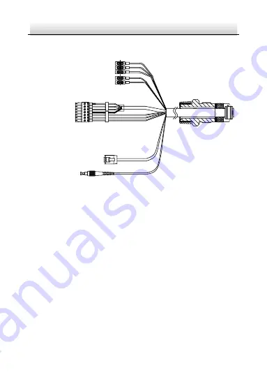
Cable Description 

7

1

Power Cord

RS-485 Cable

Audio Cable

Alarm Cable

Network Cable

Optical Fiber


Figure 1-6


Cable Description 

Notes: 


Cables vary depending on different camera models. 


The three cables of the power cord should be connected to 
corresponding wires. The red cable should be connected to live 
wire. The black cable should be connected to neutral wire. The 
yellow/green cable must be connected to the ground. 


To avoid transmitting interference, route power cables 
separately. 


DO NOT overly bend the optical fiber cable. Protect the cable 
connectors from water and dust to avoid luminous decay, 
transmission speed slowdown, and network error. 

Summary of Contents for DS-2DB4236I-CWX

Page 1: ...0 Explosion Proof IR Zoom Bullet Camera Quick Start Guide Installation Video...

Page 2: ...al The Manual includes instructions for using and managing the Product Pictures charts images and all other information hereinafter are for description and explanation only The information contained i...

Page 3: ...Y OR OTHERWISE IN CONNECTION WITH THE USE OF THE PRODUCT EVEN IF HIKVISION HAS BEEN ADVISED OF THE POSSIBILITY OF SUCH DAMAGES OR LOSS YOU ACKNOWLEDGE THAT THE NATURE OF INTERNET PROVIDES FOR INHERENT...

Page 4: ...EVELOPMENT OR PRODUCTION OF WEAPONS OF MASS DESTRUCTION THE DEVELOPMENT OR PRODUCTION OF CHEMICAL OR BIOLOGICAL WEAPONS ANY ACTIVITIES IN THE CONTEXT RELATED TO ANY NUCLEAR EXPLOSIVE OR UNSAFE NUCLEAR...

Page 5: ...requency energy and if not installed and used in accordance with the instruction manual may cause harmful interference to radio communications Operation of this equipment in a residential area is like...

Page 6: ...contains a battery that cannot be disposed of as unsorted municipal waste in the European Union See the product documentation for specific battery information The battery is marked with this symbol w...

Page 7: ...fe Use Conditions of Certification The following conditions relate to safe installation and or use of the equipment i The flameproof joints of the Explosion Proof Bullet Camera are not intended to be...

Page 8: ...he warnings are neglected Cautions Injury or equipment damage may occur if any of the cautions are neglected Warnings Laws and Regulations The device should be used in compliance with local laws elect...

Page 9: ...be connected reliably Battery This equipment is not suitable for use in locations where children are likely to be present CAUTION Risk of explosion if the battery is replaced by an incorrect type Impr...

Page 10: ...wipe the device in explosive environment Perform the wiping and replacing accessories only under non explosive environment with the glove To prevent accumulation of electrostatic charge use a soft and...

Page 11: ...Make sure that the power has been disconnected before you wire install or disassemble the device Installation could be only conducted by qualified personnel according to relevant national regulations...

Page 12: ...We shall not assume any responsibility for problems caused by unauthorized repair or maintenance A few device components e g electrolytic capacitor require regular replacement The average lifespan va...

Page 13: ...sor from dirt Using Environment When any laser equipment is in use make sure that the device lens is not exposed to the laser beam or it may burn out DO NOT aim the lens at the sun or extra bright pla...

Page 14: ...ck Start Guide xiii Time Synchronization Set up device time manually for the first time access if the local time is not synchronized with that of the network Visit the device via web browser client so...

Page 15: ...2 Type II Overview 4 1 3 3 Type III Overview 5 1 3 4 Type IV Overview 6 1 4 Cable Description 7 2 Installation 8 2 1 Run the Device in Safe Area 10 2 2 Wall Mounting with Bracket Type I 11 2 3 Wall Mo...

Page 16: ...b browser and client software Explosion proof network camera adopts a stainless steel enclosure receiving an IP68 rating for ingress protection 1 1 1 Power Supply For detailed information about the po...

Page 17: ...meet the installation requirements of the camera you purchased 1 2 Model Description The product can be named by rules as shown in Figure 1 1 Supplement Light I Infrared DS 2 x x x x x x x Hikvision F...

Page 18: ...es Type I camera Type II camera with wiper Type III camera with IR and wiper Type IV camera with IR 1 3 1 Type I Overview 4 5 1 2 3 Figure 1 2 Overview of Type I Camera Table 1 1 Description of Type I...

Page 19: ...ice case 1 3 2 Type II Overview 1 2 3 4 5 6 Figure 1 3 Overview of Type II Camera Table 1 2 Description of Type II Camera No Description No Description 1 Sun shield 4 Grounding screw 2 Transparent gla...

Page 20: ...f Type III Camera Table 1 3 Description of Type III Camera No Description No Description 1 IR 5 Grounding screw 2 Sun shield 6 Ring for safety rope 3 Transparent glass 7 Mounting base 4 Wiper Note Gro...

Page 21: ...w of Type IV Camera Table 1 4 Description of Type IV Camera No Description No Description 1 Sun shield 4 IR 2 Transparent glass 5 Ring for safety rope 3 Mounting base 6 Grounding screw Note Grounding...

Page 22: ...ee cables of the power cord should be connected to corresponding wires The red cable should be connected to live wire The black cable should be connected to neutral wire The yellow green cable must be...

Page 23: ...for standard power supply of different camera models Make sure all the related equipment is power off during the installation Check the specification of the products for the installation environment M...

Page 24: ...ing bracket included in the package You have to prepare a wall mounting bracket if you choose this mounting type The shown bracket below is only for demonstration 105 5 30 96 6 5 30 80 4 13 180 290 0...

Page 25: ...is recommended to trial run the device in the safe area before installation Steps 1 Make sure the power cable and network cable are connected properly Then power on the device to trial run the device...

Page 26: ...ng with Bracket Type I Note The camera series shares similar installation steps We take type III camera as example Steps 1 Disassemble the PT joint 2 Install the pedestal of the PT joint to the mounti...

Page 27: ...Camera 3 Install the PT joint to the wall mounting bracket with four supplied screws Note Adjust the panning position of the PT joint to desired angle when installing Pan 45 to 45 Figure 2 6 Screw the...

Page 28: ...Use at least three screws on each side of the PT joint to secure the camera Figure 2 7 Fix the Camera 5 Install the mounting base of the wall mounting bracket 1 Mark the screw holes on desired mounti...

Page 29: ...ed by the UP mark Expansion Bolt Mounting Base Nut Flat Washer Spring Washer Figure 2 9 Install the Mounting Base of the Bracket 6 Fix the wall mounting bracket together with the camera to the mountin...

Page 30: ...all Mounting Bracket to Mounting Base 2 3 Wall Mounting with Bracket Type II Note The camera series shares similar mounting steps We take type I camera as example Steps 1 Disassemble the PT joint 2 In...

Page 31: ...Pedestal Figure 2 11 PT Joint Pedestal Screws Mounting Base Figure 2 12 Install the Pedestal to Camera 3 Install the PT joint to the wall mounting bracket with four M6 16 screws Note Adjust the pannin...

Page 32: ...olts M8 100 Figure 2 14 Install Bracket to Wall 5 Fix the camera to the bracket 1 Use safety rope to hook the camera and the bracket 2 Align the screw holes on pedestal with those on PT joint Fix the...

Page 33: ...ure 2 15 Install Camera to Bracket 2 4 Protective Measures for Outdoor Installation If the device is installed outdoors necessary protective measures should be taken to ensure safety Scan the followin...

Page 34: ...the nearest service center To ensure the network security of the network camera we recommend you to have the camera assessed and maintained termly You can contact us if you need such service 3 1 Wirin...

Page 35: ...tivation via SADP and activation via client software are supported We will take activation via SADP software and activation via web browser as examples to introduce the camera activation Note For the...

Page 36: ...e a password and input the password into the password field STRONG PASSWORD RECOMMENDED We highly recommend you create a strong password of your own choosing using a minimum of 8 characters including...

Page 37: ...ord Get the SADP software from the supplied disk or the official website and install the SADP according to the prompts Follow the steps to activate the camera Steps 1 Run the SADP software to search t...

Page 38: ...in the high security system resetting the password monthly or weekly can better protect your product 4 Click Activate to save the password Note You can check whether the activation is completed on th...

Page 39: ...nt software refer to the user manual of client software Steps 1 Run the SADP software 2 Select an active device 3 Change the device IP address to the same subnet with your computer by either modifying...

Page 40: ...m Bullet Camera Quick Start Guide 25 4 Input the admin password and click Modify to activate your IP address modification The batch IP address modification is supported by SADP Refer to the user manua...

Page 41: ...ove version Steps 1 Open the web browser 2 In the browser address bar input the IP address of the network camera and enter the login interface Note The default IP address is 192 168 1 64 You are recom...

Page 42: ...a Follow the installation prompts to install the plug in Note You may have to close the web browser to finish the installation of the plug in Figure 4 2 Download Plug in 6 Reopen the web browser after...

Page 43: ...0 UD24174B A...

Reviews: