background image

3.


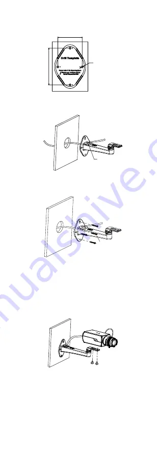
(Optional) Drill the cable hole in the wall, if you route 

the cable through the cable hole. 

54.5 mm

8

1

.6

 m

m

2-Ø  4 mm


Figure 2-1


The Drill Template


4.


Route the cables through the silicone rubber plug in 

the wall mount, and the cable hole (optional). 

Silicone rubber 

Plug


Figure 2-2


Rout the Cable 

5.


Attach the mount to the wall, and secure them with 
supplied screws. 


Figure 2-3


Attach the Back Box/Base Plate 

Note: 


The supplied screw package contains self-tapping 
screws, and expansion bolts. 


For cement wall, expansion bolts are required to fix 
the camera. For wooden wall, self-tapping screws are 
required. 

6.


Use the lock screws to secure the camera on the 
mount. 

Lock Screw


Figure 2-4


Fix the camera to the Ceiling 

7.


Connect the corresponding cables, such as power 
cord, and video cable. 

8.


Power on the camera to check whether the image on 

the monitor is gotten from the optimum angle. If not, 
adjust the camera according to the figure below to get 
an optimum angle. 

Summary of Contents for DS-2CE37U8T-A

Page 1: ...ct the dealer This manual applies to the models below Model DS 2CE37U8T A This manual may contain technical incorrect places or printing errors and the content is subject to change without notice The...

Page 2: ...eration EU Conformity Statement This product and if applicable the supplied accessories too are marked with CE and comply therefore with the applicable harmonized European standards listed under the L...

Page 3: ...noise rise from the device turn off the power at once and unplug the power cord and then contact the service center Never attempt to disassemble the camera by unprofessional personal Cautions Do not d...

Page 4: ...igh performance CMOS sensor Low illumination 0 008 Lux F1 2 AGC ON 0 Lux with IR IR cut filter with auto switch 120 dB WDR OSD menu with configurable parameters Auto white balance Internal synchroniza...

Page 5: ...roduct does not function properly contact your dealer or the nearest service center Do NOT disassemble the camera for repair or maintenance by yourself 2 1 Installing the Lens Before you start You sho...

Page 6: ...h the Back Box Base Plate Note The supplied screw package contains self tapping screws and expansion bolts For cement wall expansion bolts are required to fix the camera For wooden wall self tapping s...

Page 7: ...mplate to the celling 2 Drill screw holes in the ceiling according to the supplied drill template 66 mm 35 mm 80 mm 61 mm 4 6 mm Figure 2 6 The Drill Template 3 Secure the mount to the ceiling with su...

Page 8: ...ent 1 Loosen the adjusting knob 2 Adjust the panning positon from 0 to 360 3 Adjust tilting position from 0 to 90 4 Tighten the adjusting knob 3 Menu Description Purpose Call the menu by clicking butt...

Page 9: ...ton to adjust the value of the selected item 3 1 Video Format You can set frame rate as 8 MP 12 5fps 8 MP 15fps 5 MP 20fps 4 MP 25fps 4 MP 30fps 1080p 25fps or 1080p 30fps 3 2 Language Supports Englis...

Page 10: ...strong When BLC is selected as the exposure mode the BLC level can be adjusted from 0 to 8 HLC High Light Compensation HLC High Light Compensation masks strong light sources that usually flare across...

Page 11: ...W The image is black and white all the time Auto The image switches from color to B W or from B W to color automatically according to the light conditions EXT Switch to the EXT mode when the device c...

Page 12: ...lly Defog It is used in special environments such as the foggy or rainy weather or in high illumination conditions in which the dynamic range is lower than that in the ordinary environment and the ima...

Reviews: