Network Dome Camera
·
Quick Start Guide
28
28
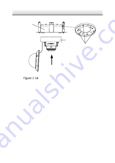
In-ceiling Mounting
Bracket
Camera
Mounting Base
Screw Holes for
Camera Fixing
Install the Camera to the Mounting Base
4.
Place the bracket and camera to the hole in ceiling, and screw the
toggle bolt clockwise to fix the bracket in ceiling.


